Solid sample, solid sample fabricating method, and solid sample fabricating apparatus

Inactive Publication Date: 2008-11-27
CANON KK
View PDF2 Cites 26 Cited by
  • Summary
  • Abstract
  • Description
  • Claims
  • Application Information

AI Technical Summary

Benefits of technology

[0013]The present invention provides a solid sample enabling the dispersion state of a solid or liquid dispersive substan

Problems solved by technology

However, since the SEM requires a sample to be placed in a vacuum, an ordinary sample cannot be observed in a liquid state.
Further, when the sample is very small, it is difficult to make the heat capacity of the holder smaller than that of the sample.
Further, the liquid sample cannot be entirely incorporated int

Method used


Image

  • Solid sample, solid sample fabricating method, and solid sample fabricating apparatus
  • Solid sample, solid sample fabricating method, and solid sample fabricating apparatus
  • Solid sample, solid sample fabricating method, and solid sample fabricating apparatus

Examples


first exemplary embodiment

[0093]A first exemplary embodiment of the present invention is described below with reference to the drawings.

Sample Fabricating Apparatus 1

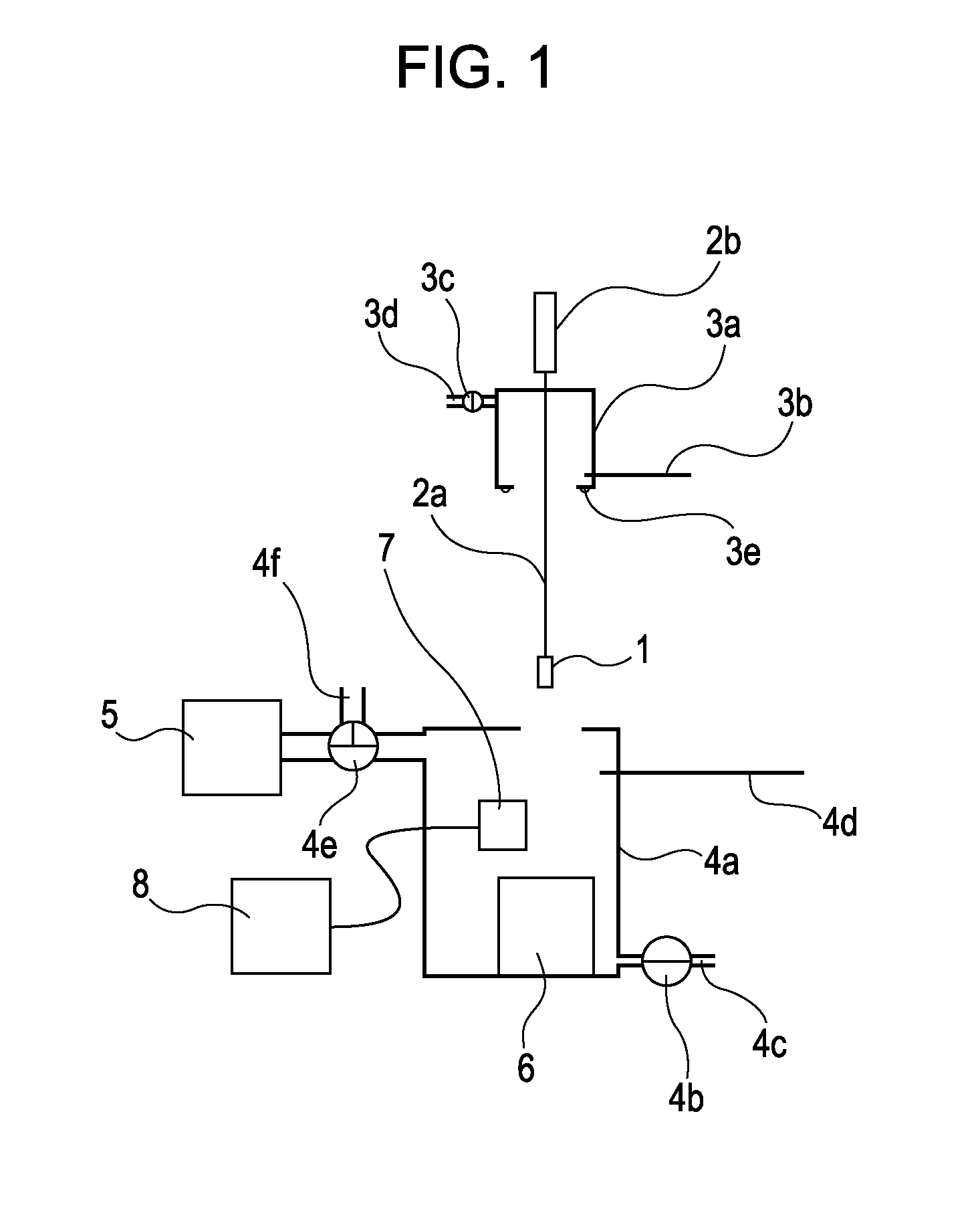
[0094]FIG. 1 illustrates one example of the sample fabricating apparatus according to the present invention in which a liquid jet head is employed as a specimen supply unit.

[0095]A stage 1 on which a sample is placed is attached to an introduction rod 2a, and an operating portion 2b is connected to a top end of the introduction rod 2a. The stage 1 can be made of a substance that has a large specific heat and high thermal conductivity, specifically a metal such as aluminum or copper. A thin aluminum oxide film can be formed on the surface of the stage 1.

[0096]A temperature sensor (not shown) is built in the stage 1 such that it can be connected from the interior of the introduction rod 2a to a temperature display unit or an externally installed temperature controller (not shown).

[0097]The stage 1 is extended from a first chamber 3a (hereinafter r...

second exemplary embodiment

Sample Observing Apparatus 1

[0135]A sample observing apparatus according to a second exemplary embodiment is described below. The sample observing apparatus is an apparatus in which a sample fabricating apparatus and a cross-section machining and observing apparatus are integrally combined with each other.

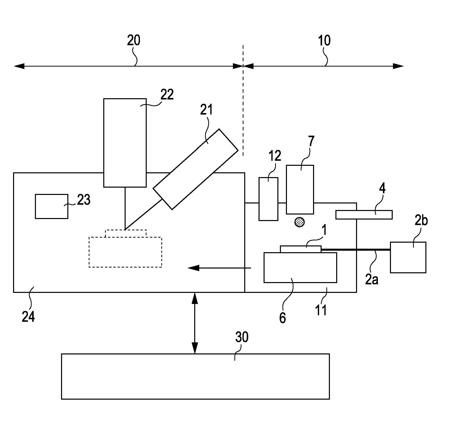
[0136]FIG. 6 illustrates a construction of an FIB-SEM apparatus for observing the cross-section, which includes the sample fabricating apparatus, according to this exemplary embodiment. The FIB-SEM apparatus of FIG. 6 is constituted by a sample fabricating section 10, a machining and observing section 20, and a control section 30. The second exemplary embodiment differs from the first exemplary embodiment in that the sample fabricating section is added as a pre-processing chamber for the FIB-SEM apparatus.

[0137]As in the sample fabricating apparatus of FIG. 1, the sample fabricating section 10 includes a movable stage 1 on which a sample is placed, a stepping motor 2b as a moving m...

third exemplary embodiment

Sample Observing Apparatus 2

[0157]FIG. 9 illustrates the structure of a sample observing apparatus according to a third exemplary embodiment. In the apparatus of FIG. 9, instead of the liquid jet head, a specimen supply unit 13 having a hollow tube disposed at its bottom end is disposed as the specimen supply unit in the pre-processing chamber 11. The other components are the same as those in the sample observing apparatus of FIG. 6.

[0158]A liquid sample held as a specimen in the hollow tube is pressurized by a pressurizing apparatus (not shown) and is ejected through an ejection orifice formed at a distal end of the hollow tube. The ejected sample flies in the form of a droplet and is attached to the stage surface.


PUM

PropertyMeasurementUnit
Temperatureaaaaaaaaaa
Heightaaaaaaaaaa

Abstract

A solid sample fabricating method includes preparing a specimen containing a first substance, which is in a liquid phase at normal temperature and normal pressure, and a second substance different from the first substance, which is in a solid or a liquid phase at the normal temperature and the normal pressure, the second substance being dispersed in the first substance, and attaching the specimen as a droplet to a surface of a cooled stage, whereby an entire region to be observed is converted into an amorphous state.

Description

BACKGROUND OF THE INVENTION[0001]1. Field of the Invention[0002]The present invention relates to a solid sample that allows the dispersion state of a substance, which is dispersed in a liquid, to be observed with a higher level of accuracy, and to methods of fabricating and observing the solid sample. Also, the present invention relates to apparatuses for use with the solid sample fabricating and observing methods.[0003]2. Description of the Related Art[0004]With a recent increase in needs for functional devices, there is a demand for a more accurate evaluation and a finer structural analysis of the dispersion state of a sample in which a solid or liquid substance is dispersed in a liquid medium, such as drugs and emulsions.[0005]An SEM (Scanning Electron Microscope) is generally used to observe structures smaller than those observable by an optical microscope. However, since the SEM requires a sample to be placed in a vacuum, an ordinary sample cannot be observed in a liquid state....

Claims


Application Information

Patent Timeline
IPC IPC(8): B01J13/00B01L11/00B01L99/00G01N1/28H01J37/20
CPCG01N1/42H01J37/20H01J2237/2001H01J2237/2002H01J2237/20285H01J2237/2065H01J2237/28H01J2237/31H01J2237/31749
Inventor YOKOI, HIDETOMOTOI, TAIKOSUZUKI, TOMOKO
Owner CANON KK
Why Eureka
Try Eureka