Integrated gasification combined cycle power generation plant

a combined cycle and gasification technology, applied in the direction of combustible gas production, machines/engines, mechanical equipment, etc., can solve the problems of reduced plant efficiency, increased restrictions on high provisions, and difficulty in facility design of igcc, so as to facilitate further plant efficiency and reduce the pressure of the supply system for gasifying agents.

Inactive Publication Date: 2008-12-04
MITSUBISHI HEAVY IND LTD
View PDF4 Cites 25 Cited by
  • Summary
  • Abstract
  • Description
  • Claims
  • Application Information

AI Technical Summary

Benefits of technology

[0039]The present invention has advantages in that the pressure and flow quantity of the gasifying agent to be supplied to the gasifying fur...

Problems solved by technology

Therefore, a problem can arise wherein a pressure drop with the control valve 118 can occur, resulting in plant efficiency decrease.
Accordingly, not o...

Method used


Image

  • Integrated gasification combined cycle power generation plant
  • Integrated gasification combined cycle power generation plant
  • Integrated gasification combined cycle power generation plant

Examples


first embodiment

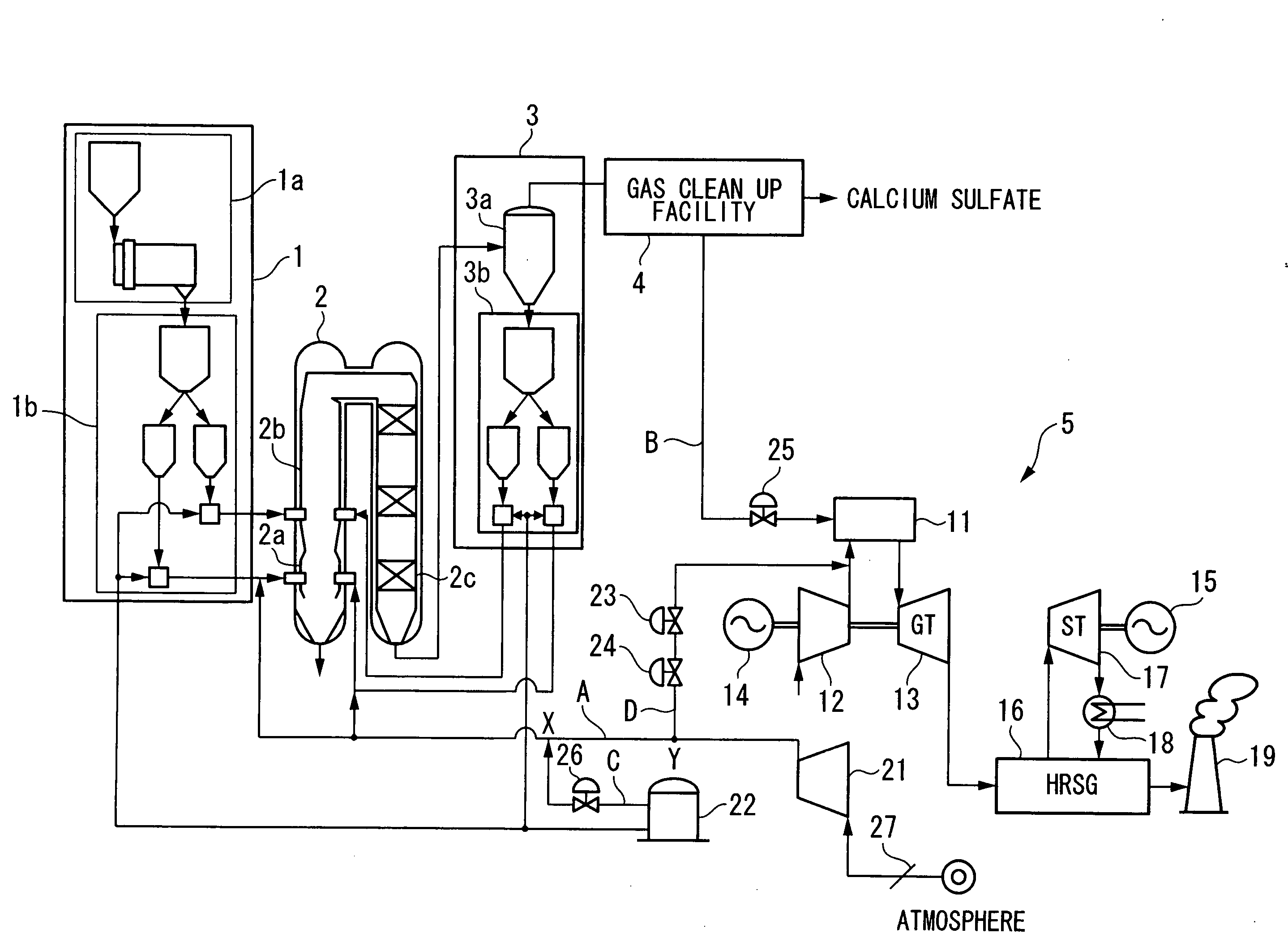
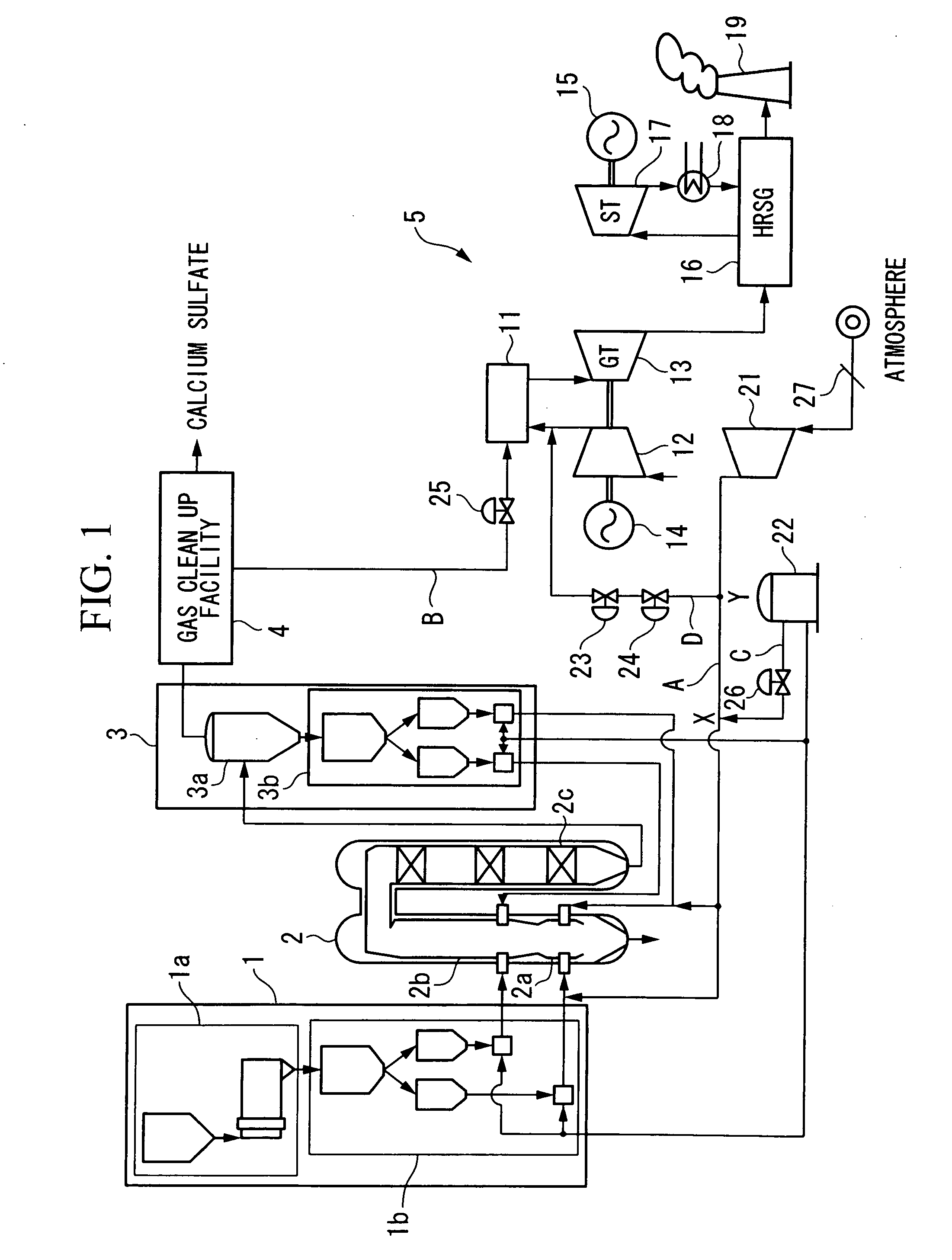
[0071]A first embodiment of the present invention will be described with reference to the diagrams. FIG. 1 is a block diagram illustrating a schematic configuration of an IGCC according to the present invention. The IGCC according to the present embodiment employs an air-blowing method to supply air as the gasifying agent.

[0072]As shown in FIG. 1, the IGCC relating to the present embodiment primarily comprises a coal supply facility 1, a gasifying furnace 2, a dust removal facility 3, a gas clean up facility 4, and a power generating facility 5.

(Coal Supply Facility 1)

[0073]The coal supply facility 1 comprises a pulverizer 1a which pulverizes coal accumulated in a raw coal bunker with a mill into pulverized coal of several μm to several hundred μm, and a pulverized coal supply device 1b which supplies the pulverized coal pulverized with the pulverizer 1a to the gasifying furnace 2. With the coal supply facility 1 thus configured, the pulverized coal obtained by pulverizing coal with...

second embodiment

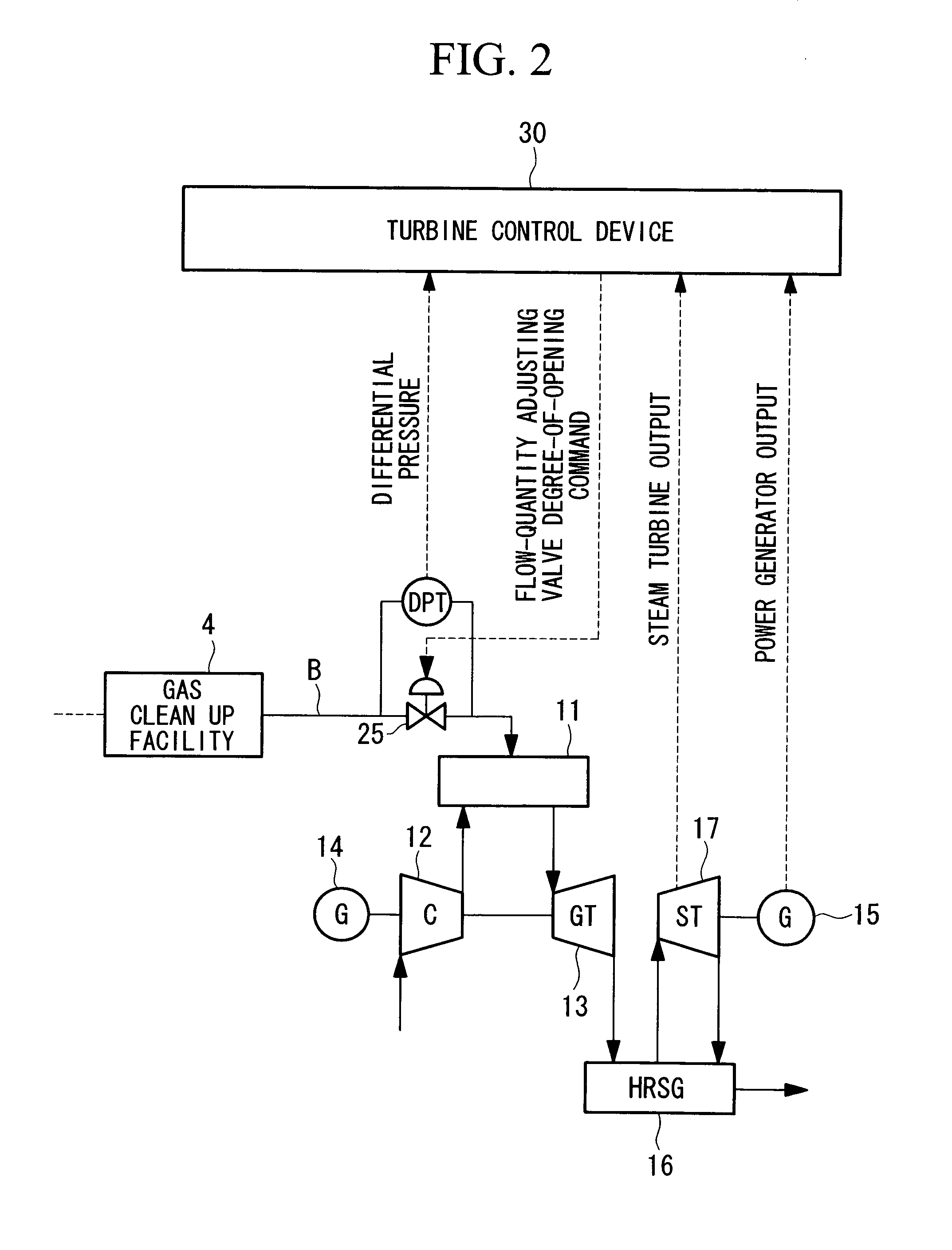
[0116]Next, a second embodiment according to the present invention will be described. With the IGCC relating to the above-described first embodiment, the flow-quantity adjusting valve 25 (see FIG. 1) is provided to adjust the flow quantity of the flammable gas supplied to the combustor 11 on the flammable gas supply path B. The IGCC relating to the present embodiment differs from the IGCC related to the above-described first embodiment in the points wherein the flow-quantity adjusting valve 25 is removed, as shown in FIG. 7.

[0117]Thus, with the IGCC relating to the present embodiment, since the flow-quantity adjusting valve 25 is not provided herein, the flow quantity adjustment of flammable gas to the combustor 11 is performed by the controls of the gasifying furnace 2. Hereafter, the control method of the IGCC relating to the present embodiment will be described in detail.

[0118]FIG. 8 is a diagram illustrating a configuration with a gasifying furnace control device 50-1 relating t...

first modification

[0126]With the above-described embodiments, the IGV degree of opening setting unit 56 with the gasifying furnace control device 50 and 50-1 may further comprise a first correcting unit 563 to correct the IGV degree-of-opening command in the direction to increase the volume of air supplied to the axial flow compressor 21 according to functional decline by aged deterioration of the axial flow compressor 21.

[0127]FIG. 11 is a block diagram illustrating a schematic configuration of the IGV degree of opening setting unit relating to the first modification of the present invention. As shown in FIG. 11, the first correcting unit 563 includes a subtractor 62 to obtain the air quantity which is somewhat less than the requested air quantity as the corrected air request quantity by obtaining the difference between the requested air quantity set based on the gasifying furnace overall command GID and the adjusted value output from a signal generator 61 (e.g. flow quantity deviation quantity to s...


PUM


Abstract

A gasifying agent supply path A from an axial flow compressor 21 which boosts pressure of a gasifying agent to a gasifying furnace 2 is branched, and a gasifying agent bypass path D having an escaping pressure adjusting valve 23 is provided. The flow quantity or pressure of the gasifying agent supplied to the gasifying furnace 2 from the gasifying agent supply path A can be adjusted according to the degree of opening of the adjusting valve 23 disposed in the gasifying agent bypass path D, whereby providing a control valve in the gasifying agent supply path A is no longer necessary. Thus, pressure loss at the gasifying agent supply path A can be suppressed, and the discharge pressure of the axial flow compressor 21 can be greatly reduced.

Description

CROSS-REFERENCE TO RELATED APPLICATIONS[0001]This application claims the benefit of U.S. Provisional Application No. 60 / 924,756, filed May 30, 2007.BACKGROUND OF THE INVENTION[0002]1. Field of the Invention[0003]The present invention relates to an integrated gasification combined cycle power generation plant (hereafter, “IGCC”) which drives a gas turbine with flammable gas obtained by gasifying a solid fuel such as coal, and the operation control apparatus and method thereof.[0004]2. Description of Related Art[0005]As a power generation plant using gas turbines, an IGCC (Integrated Gasification Combined Cycle) which employs fossil fuels such as coal for fuel gas is known. With an IGCC, solid fuel is gasified by causing a high temperature gas agent to come in contact with a solid fuel in powder form in a gasifying furnace, thereby generating flammable gas. This flammable gas is then supplied to a combustor of a gas turbine, whereby the gas turbine is rotationally driven, and the rota...

Claims


Application Information

Patent Timeline
IPC IPC(8): F02C6/00F02C9/26
CPCC10J3/00C10J3/466C10J3/723C10J3/84C10J2300/093C10J2300/0956C10J2300/0959C10J2300/165C10J2300/1671C10J2300/1675C10J2300/1678C10J2300/1884F01K23/068F02C3/28Y02E20/18Y02E20/16C10J3/02F02C7/22F02C9/28
Inventor HYAKUTAKE, YOSHINORITSUKUDA, YOSHIAKIHASHIMOTO, TAKAOUCHIDA, SATOSHIOTA, KATSUHIROSONODA, TAKASHI
Owner MITSUBISHI HEAVY IND LTD
Why Eureka
Try Eureka