
Fluid Storage and Purification Method and System

Inactive Publication Date: 2008-12-04
MATHESON TRI GAS
View PDF0 Cites 13 Cited by
  • Summary
  • Abstract
  • Description
  • Claims
  • Application Information

AI Technical Summary

Benefits of technology

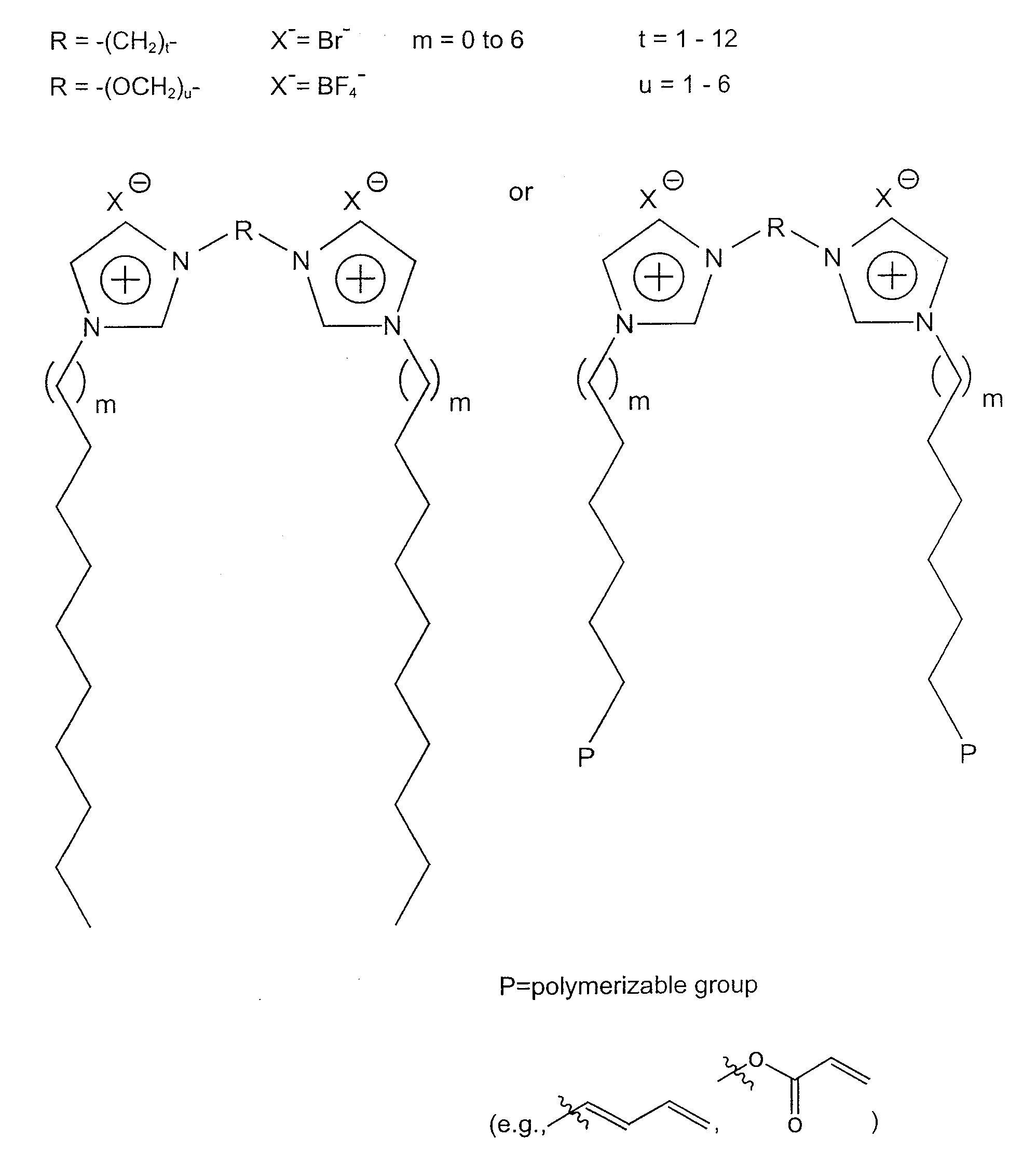
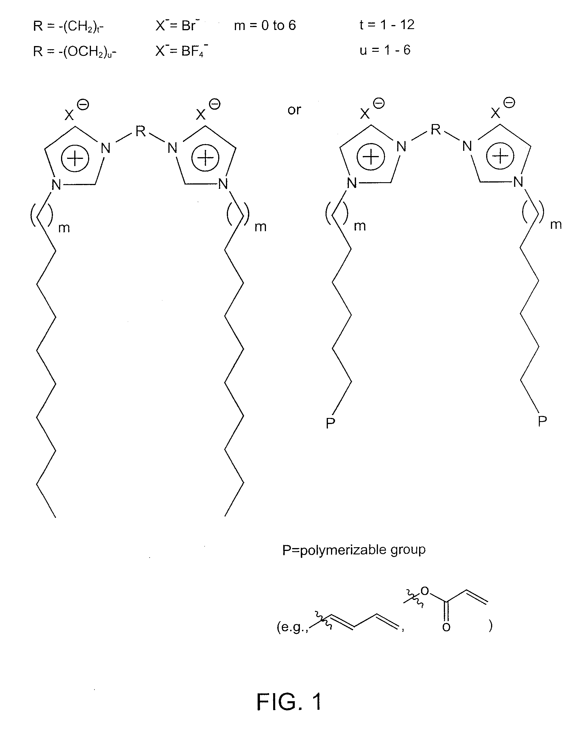
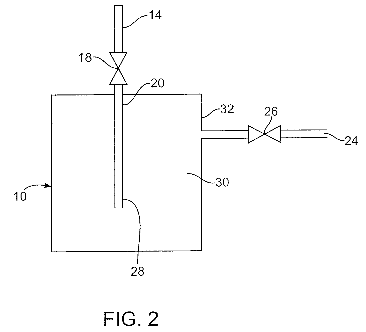
[0010]In one aspect of the invention, a method of storing and dispensing a fluid is provided. The method includes providing a vessel having a nanocomposite material within, that may be optionally polymerized, wherein the vessel is configured for maximized storage of the fluid therein. The nanocomposite material is configured to maximize its surface area and comprises a surfactant, such as but not limited to, a polymerizable cationic imidazolium and an integral solvent that is essential to the formation of the polymerized nanocomposite material. The solvent may be, but is not limited to, either water, room temperature ionic liquids (RTILS), other solvents or mixtures thereof and when mixed with a cationic imidazolium surfactant, nanostructured, phase-separated lyotropic liquid crystal (LLC) phases are formed. Of particular interest are bicontinuous cubic (Q) LLC phases which possess high accessible surface area due to 3-D interconnected solvent and LLC surfactant domains. However, other nanostructured LLC phases such as the inverted hexagonal, lamellar, and other types of cubic LLC phases formed by the aforementioned polymerizable cationic imidazolium surfactants, are also of interest. The resulting polymerized nanocomposite material is positioned within the vessel

Problems solved by technology

These gases pose significant safety and environmental challenges due to their high toxicity and reactivity.
Additionally, storage of hazardous gases under high pressure in metal cylinders is often unacceptable because of the possibility of developing a leak or catastrophic rupture of the cylinder, cylinder valve, or downstream component.
Additionally, some gases, such as diborane, tend to decompose when stored for a period of time.
These impurities can cause defects that reduce yields by increasing the number of rejects, which can be very expensive.
Although source gas manufacturers typically provide analyses of source gas materials delivered to the semiconductor manufacturing facility, the purity of the gases may change because of leakage into or outgassing of the containers, e.g. gas cylinders, in which the gases are packaged.
Impurity contamination may also result from improper gas cylinder changes, leaks into downstream processing equipment, or outgassing of such downstream equipment.
Furthermore, the impurity levels within the gas container may increase with length of storage time and can also change as the container is consumed by the end user.

Method used


Image

  • Fluid Storage and Purification Method and System
  • Fluid Storage and Purification Method and System
  • Fluid Storage and Purification Method and System

Examples


example 1

Storage of a Gas Using Nanocomposite Material in which the Solvent is an Ionic Liquid—BF3 Stored in poly[1,1′-[1,2-ethanediylbis(oxy-2,1-ethanediyl)]-2,2′-undecyl-3,3′-(undecyl-11-acryloyloxy-bisimidazolium di-tetrafluoroborate]; 1-ethyl-3-methylimidazolium tetrafluoroborate

[0106]A stainless steel canister is charged with a known quantity of the nanocomposite material poly(1,1′-[1,2-ethanediylbis(oxy-2,1-ethanediyl)]-2,2′-undecyl-3,3′-(undecyl-11-acryloyloxy)-bisimidazolium di-tetrafluoroborate); 1-ethyl-3-methylimidazolium tetrafluoroborate. The charged canister is thermally controlled by a PID temperature controller or variac with a heating element and a thermocouple. The canister is placed on a gravimetric load cell or weight scale and a pressure gauge is connected to the canister to measure head pressure. This canister is connected to a manifold with vacuum capability and to a gas source. The canister is also connected to an analyzer (such as FT-IR, GC, APIMS, etc.).

[0107]A vacu...

example 2

Storage of a Gas Using Nanocomposite Material in which the Solvent is a Molecular Solvent—BF3 Stored in poly[1,1′-[1,2-ethanediylbis(oxy-2,1-ethanediyl)]-2,2′-undecyl-3,3′-(undecyl-11-acryloyloxy)-bisimidazolium dibromide].H2O

[0110]A stainless steel canister is charged with a known quantity of the nanocomposite material poly[1,1′-[1,2-ethanediylbis(oxy-2,1-ethanediyl)]-2,2′-undecyl-3,3′-(undecyl-11-acryloyloxy)-bisimidazolium dibromide].H2O. The charged canister is thermally controlled by a PID temperature controller or variac with a heating element and a thermocouple. The canister is placed on a gravimetric load cell or weight scale and a pressure gauge is connected to the canister to measure head pressure. This canister is connected to a manifold with vacuum capability and to a gas source. The canister is also connected to an analyzer (such as FT-IR, GC, APIMS, etc.).

[0111]A vacuum bake procedure is conducted on the canister, charged with poly[1,1′-[1,2-ethanediylbis(oxy-2,1-ethan...

example 3

Storage of a Gas Using Nanocomposite Material in which the Solvent is a Mixture of Ionic Liquid and Molecular Solvent—BF3 Stored in poly[1,1′-[1,2-ethanediylbis(oxy-2,1-ethanediyl)]-2,2′-undecyl-3,3′-(undecyl-11-acryloyloxy-bisimidazolium di-bromide]1-ethyl-3-methylimidazolium bromide.H2O

[0114]A stainless steel canister is charged with a known quantity of the nanocomposite material poly[1,1′-[1,2-ethanediylbis(oxy-2,1-ethanediyl)]-2,2′-undecyl-3,3′-(undecyl-11-acryloyloxy)-bisimidazolium di-bromide].1-ethyl-3-methylimidazolium bromide.H2O. The charged canister is thermally controlled by a PID temperature controller or variac with a heating element and a thermocouple. The canister is placed on a gravimetric load cell or weight scale and a pressure gauge is connected to the canister to measure head pressure. This canister is connected to a manifold with vacuum capability and to a gas source. The canister is also connected to an analyzer (such as FT-IR, GC, APIMS, etc.).

[0115]A vacuum ...


PUM


Abstract

A method and device for storing and dispensing a fluid includes providing a vessel configured for selective dispensing of the fluid therefrom. Provided within a vessel is a nancomposite material comprising an imidazolium surfactant and an integral solvent that is essential to the formation of the nancomposite material. The fluid is contacted with the nanocomposite material for take-up of the fluid by the polymerized nanocomposite material. The fluid is released from the nanocomposite material and dispensed from the vessel.

Description

CROSS REFERENCE TO OTHER APPLICATIONS[0001]This application claims benefit of priority to two provisional U.S. Application Nos. 60 / 806,524, filed Jul. 3, 2006, and 60 / 892,807, filed Mar. 2, 2007, the disclosures of which are fully incorporated herein by reference.BACKGROUND OF THE INVENTION[0002]1. Field of the Invention[0003]The present invention relates to a method of storing a fluid, and more particularly to a vessel having a nanocomposite material, that may optionally be polymerized, comprising a surfactant and an integral solvent that is essential to the formation of the nanocomposite material. The surfactant may be, but is not limited to, a polymerizable cationic imidazolium surfactant that can form ordered, nanostructured, phase-segregated lyotropic liquid crystal (LLC) phases when mixed with either water, room temperature ionic liquids (RTILS), other solvents or mixtures of said liquids. The LLC phases formed may be, but are not limited to, special bicontinuous cubic (Q) typ...

Claims


Application Information

Patent Timeline
IPC IPC(8): C07D403/04C07D233/58B65D90/02
CPCC01B7/01C01B7/20C01B13/0281C07D403/06C07D403/12F17C11/00F17C11/005Y10T137/0318
Inventor WYSE, CARRIE L.TORRES, ROBERTMILLWARD, ANDREW R.NOBLE, RICHARD D.BARA, JASON EDWARDGIN, DOUGLAS
Owner MATHESON TRI GAS
Learn More