Methods and apparatus for optical analysis of samples in biological sample containers

an automatic analysis and biological sample technology, applied in the field of biological sample container optical analysis, can solve the problems of insufficient optical feedback in the autofocus system to function efficiently, time-consuming to refocus the camera for each well, and inconvenient slowness for an automated system intended to handle many cell samples. , to achieve the effect of very rapid and accurate determination of focal plane and known very accurately

Active Publication Date: 2008-12-04
GENETIX LTD
View PDF8 Cites 35 Cited by
  • Summary
  • Abstract
  • Description
  • Claims
  • Application Information

AI Technical Summary

Benefits of technology

[0024]The predetermined relationship between wavelength and position on the optical axis can be known in advance very accurately by factory calibration, and thus the position of an intersection between the base of the sample container and the optical axis can also be known very accurately by detecting the wavelength of reflected light. In this way, the measured position of the base on the optical axis can be used as a reference for accurately determining a focal plane for imaging samples within the sample container. This method of determining the position of the base of a sample container is particularly suitable because it can be achieved very rapidly compared with conventional autofocus and

Problems solved by technology

This is problematic, since the volume of liquid solution varies and thus the height of the upper surface of the liquid.
However, for a container requiring many images, such as a well plate comprising 96, 384 or 1536 wells, it can be very time-consuming to refocus the camera for each well.
This is particularly problematic if no stains or fluorescent tags are used to highlight the cells; the visual contrast between the cells and their surroundings can be insufficient for the optical feedback in the autofocus system to function efficiently.
As an example, under these conditions it ca

Method used


Image

  • Methods and apparatus for optical analysis of samples in biological sample containers
  • Methods and apparatus for optical analysis of samples in biological sample containers
  • Methods and apparatus for optical analysis of samples in biological sample containers

Examples


Embodiment Construction

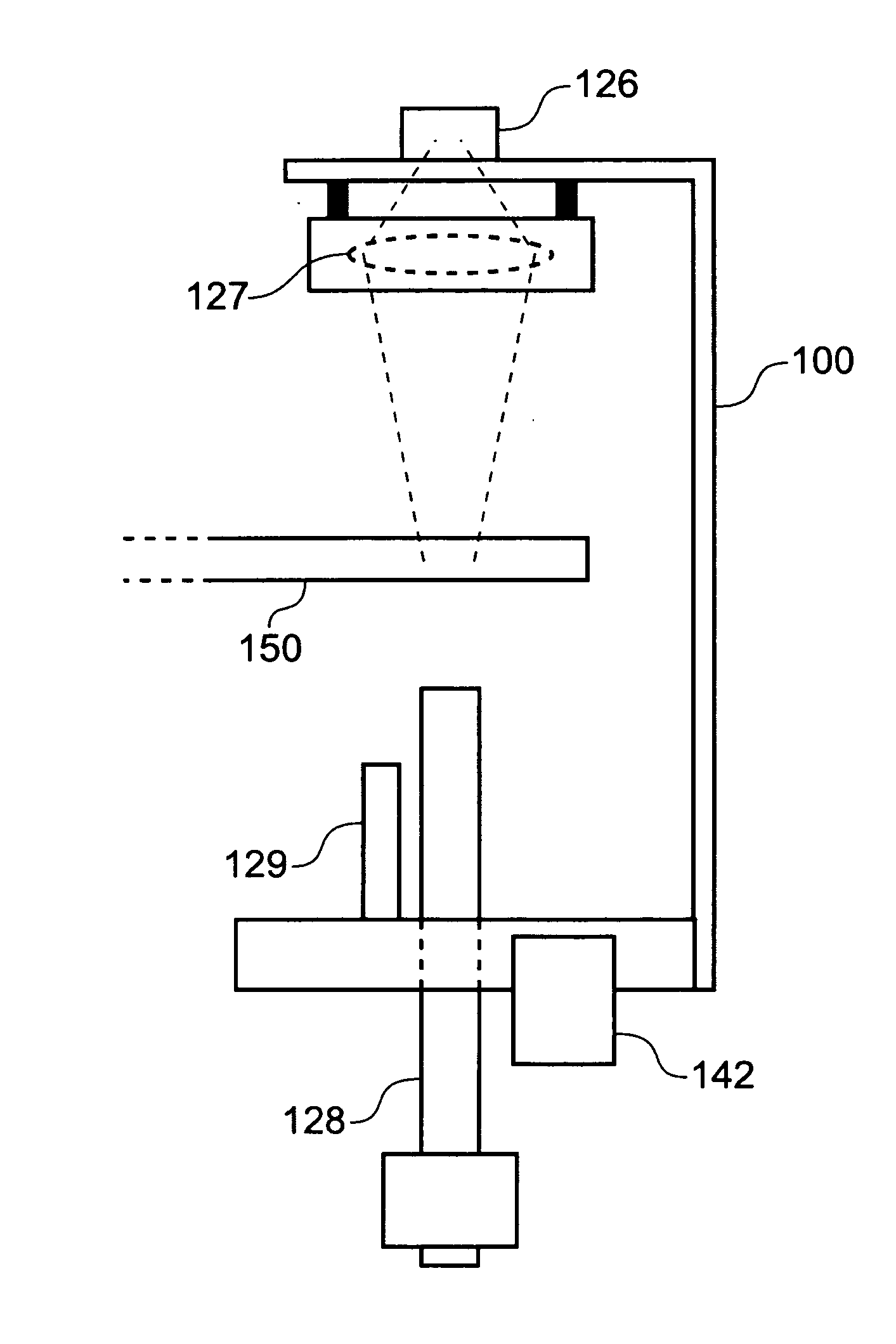
[0072]FIG. 5 is a perspective view of an apparatus for handling and processing biological samples that embodies aspects of the present invention. However, it is to be understood that the various aspects of the invention may be used with alternative apparatus, containing fewer or more features for handling and processing samples and / or for handling samples in alternative biological sample containers.

[0073]The apparatus 110 may be understood as a robot for cell picking having an integrated imaging camera. The apparatus can be subdivided notionally into two-half spaces, one above and one below a main bed 112 which is supported by a frame 114. The main bed 112 is mounted on linear positioners (not shown) so as to be movable relative to the frame 114 in the x and y directions, under the control of a controller (not shown). The controller may be a computer connected by electronic links using standard interface protocols to various automated components of the apparatus 110, with control of...


PUM


Abstract

An apparatus and method for optically analyzing samples in a biological sample container containing samples arranged at different locations on the base of the container. An optical acquisition device is provided comprising a detector and an objective. The position of the upper and lower surfaces of the base at each of the sample locations is determined by a confocal polychromatic displacement sensor. Light is collected from each of the sample locations by adjusting the focal plane to be coincident with, or vertically offset from, the upper surface of the base, as determined from the displacement sensor. This allows for rapid scanning of large numbers of samples in a multi-well plate or other biological sample containers.

Description

BACKGROUND OF THE INVENTION[0001]The present invention relates to automated methods and apparatus for optically analyzing samples in biological sample containers such as well plates.[0002]Biological samples such as animal cells, in particular mammalian cells, are commonly cultured in biological sample containers such as well plates (sometimes called microtiter plates or microplates), omni trays, Q-trays and Petri dishes. Much of the processing of the samples can be performed automatically using robotic apparatus that can deliver containers to and from various stations at which the samples can be observed and imaged using camera equipment, and transferred to other containers using an array of pins on a movable mechanical head.[0003]FIGS. 1A and 1B schematically illustrate an example biological sample container 1 in the form of a well plate with a plurality of wells 5 in a 4×3 array. More typically a well plate used for automated processes on a robotic platform will have an array of w...

Claims


Application Information

Patent Timeline
IPC IPC(8): G01J1/00G01N33/48
CPCB01L3/5085G01N19/08G01N21/253G01B11/06C12M23/12C12M41/36
Inventor JIANG, YONGGANG
Owner GENETIX LTD
Why Eureka
Try Eureka