Multi-engine system with on-board ammonia production

a multi-engine, ammonia production technology, applied in the direction of machines/engines, electrical control, separation processes, etc., can solve the problems of limiting the nox reduction capability of the system, difficult to replenish ammonia, and difficult to stor

Inactive Publication Date: 2008-12-11
CATERPILLAR INC
View PDF5 Cites 17 Cited by
  • Summary
  • Abstract
  • Description
  • Claims
  • Application Information

AI Technical Summary

Benefits of technology

[0010]The disclosed system is directed to overcoming one or more of the problems set forth above.

Problems solved by technology

Fossil fuel powered systems for engines, factories, and power plants typically produce emissions that contain a variety of pollutants.
However, because of the high reactivity of ammonia, storage can be problematic.
In addition, machines utilizing SCR systems sometimes operate in remote locations where it may be difficult to replenish the ammonia.
Although the system in the '088 patent may reduce NOx emissions, the utilization of lean exhaust gas or a burner to generate ammonia may limit the NOx reducing capability of the system.
In particular, with respect to the first embodiment, the lean exhaust gas contains a large amount of oxygen which adversely affects the production of ammonia.
Thus, the combination of the rich exhaust gas with the lean exhaust gas before the exhaust gas is converted to ammonia limits the amount of ammonia that can be produced.
With respect to the second embodiment, the burner combusts the rich air / fuel mixture at a temperature that is unfavorable for NOx production, thereby limiting ammonia generation.
NOx reduction in both embodiments is limited because only a limited amount of ammonia is available to react with the SCR catalytic device.
In addition, the engine system disclosed in the '088 patent consumes a larger amount of fuel to produce a particular mechanical or electrical output than a conventional power system without on-board ammonia production.
Therefore, energy from the additional fuel is used solely to produce ammonia and is not used to accomplish the task being performed by the main engine.
By using the additional fuel, operational costs may increase and the system efficiency may decrease.

Method used


Image

  • Multi-engine system with on-board ammonia production
  • Multi-engine system with on-board ammonia production
  • Multi-engine system with on-board ammonia production

Examples


Embodiment Construction

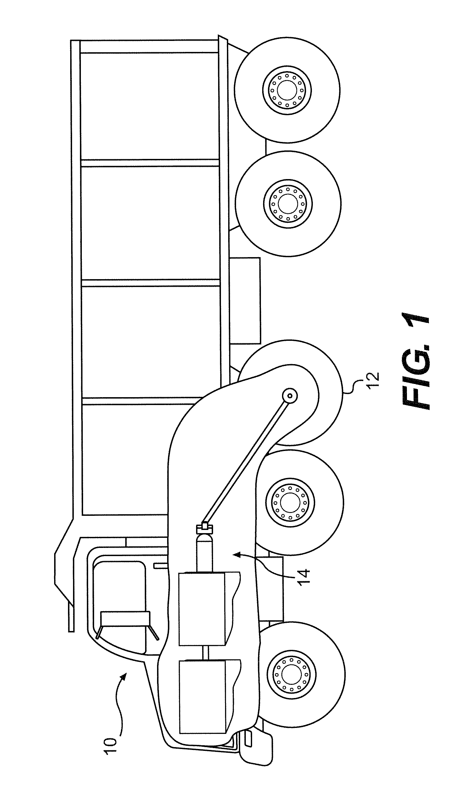
[0018]FIG. 1 illustrates an exemplary machine 10 having multiple systems and components that cooperate to accomplish a task. The tasks performed by machine 10 may be associated with a particular industry such as mining, construction, farming, transportation, power generation, or any other industry known in the art. For example, machine 10 may embody a mobile machine such as, a bus, a haul truck, a locomotive, a marine vessel, or any other type of machine known in the art. As shown in FIG. 1, machine 10 may include one or more traction devices 12 operatively connected to and driven by a power train 14.

[0019]Traction devices 12 may embody wheels located on each side of machine 10 (only one side shown). Alternatively, traction devices 12 may include tracks, belts or other known traction devices. It is contemplated that any combination of the wheels on machine 10 may be driven and / or steered.

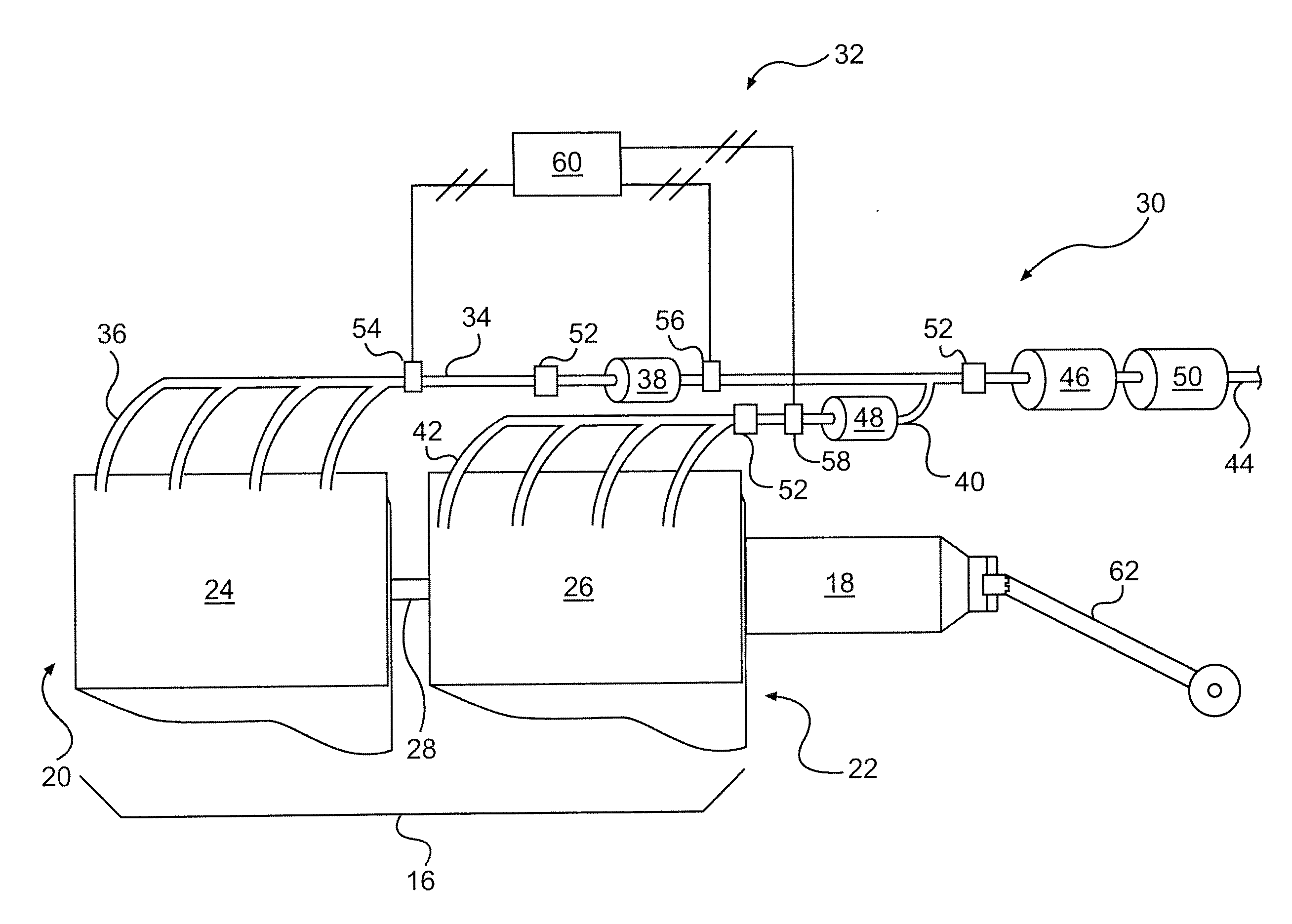
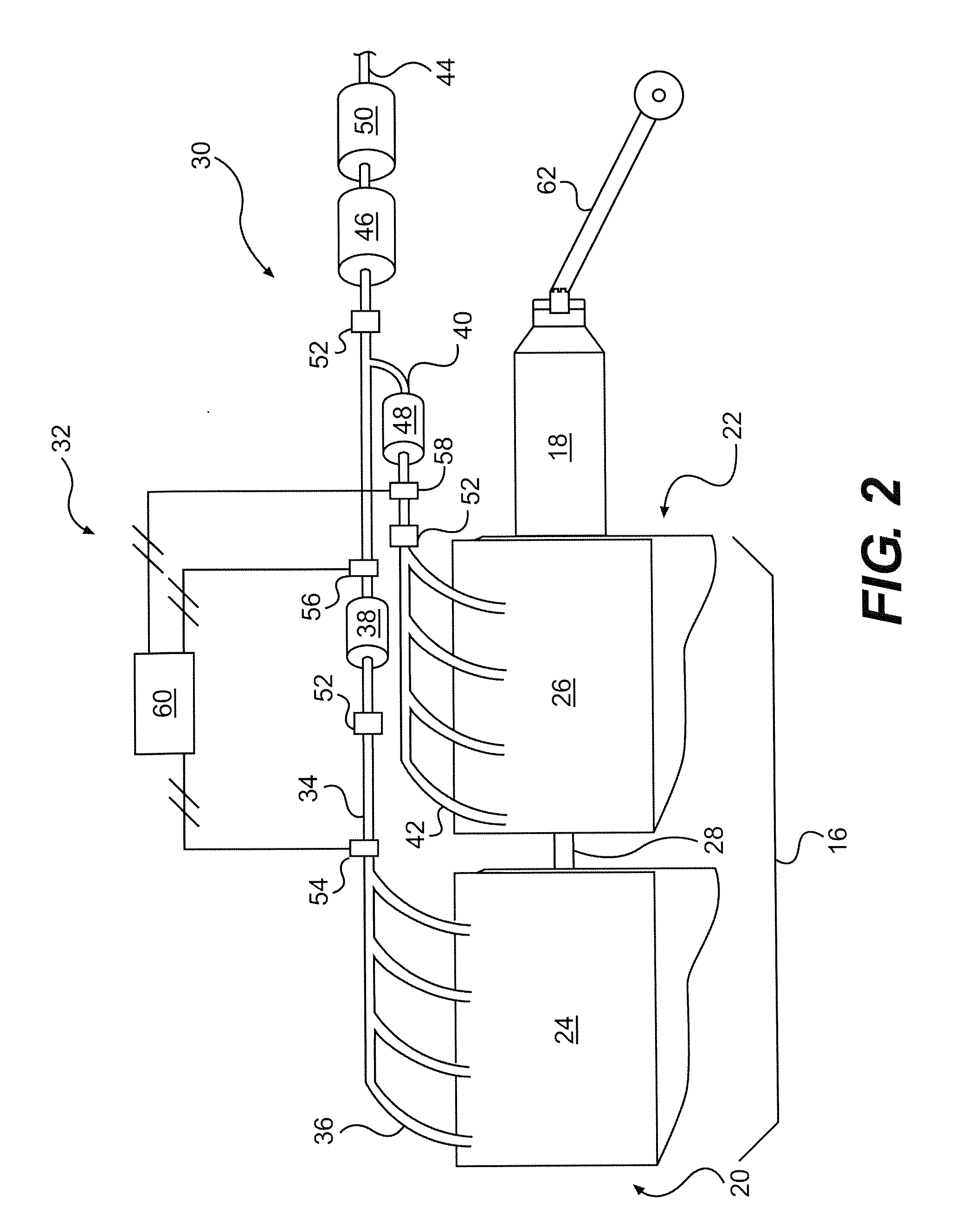
[0020]Power train 14 may be an integral package configured to generate and transmit power to tra...


PUM

PropertyMeasurementUnit
poweraaaaaaaaaa
electrical energyaaaaaaaaaa
sizeaaaaaaaaaa

Abstract

A power system is provided having a first power source including at least one engine configured to combust a first air/fuel mixture and produce a first exhaust stream. The fuel of the first air/fuel mixture may be liquefied petroleum gas. The system also has a first exhaust passageway fluidly connected to the first power source and configured to receive the first exhaust stream. In addition, the system has a second power source including at least one engine configured to combust a second fuel/air mixture and produce a second exhaust stream. Furthermore, the system has a second exhaust passageway fluidly connected to the second power source and configured to receive the second exhaust stream. The system further has a first catalyst disposed within the first exhaust passageway to convert at least a portion of the first exhaust stream to ammonia

Description

RELATED APPLICATIONS[0001]This application is a continuation-in-part of U.S. patent application Ser. No. 11 / 806,384, filed May 31, 2007, the entire contents of which are incorporated herein by reference.STATEMENT OF GOVERNMENT INTEREST[0002]This invention was made with Government support under Contract No. DE-FC26-01CH1107 awarded by the Department of Energy. The Government may have certain rights in this invention.TECHNICAL FIELD[0003]The present disclosure is directed to a multi-engine system and more particularly, to a multi-engine system with at least one engine having an on-board ammonia producing capability.BACKGROUND[0004]Fossil fuel powered systems for engines, factories, and power plants typically produce emissions that contain a variety of pollutants. These pollutants may include, for example, particulate matter, nitrogen oxides (NOx), and sulfur compounds. Due to heightened environmental concerns, exhaust emission standards have become increasingly stringent. The amount o...

Claims


Application Information

Patent Timeline
Patent Type & Authority Applications(United States)
IPC IPC(8): F01N3/20B61C3/00
CPCB01D53/9409B01D2251/2062B01D2258/012B01D2258/014B61C17/00F01N3/2073F01N2240/25F01N2560/021F01N2560/026F01N2590/08F02D25/00F02D41/0235Y02A50/20
Inventor MONTGOMERY, DAVID TODDGONG, WEIDONGROBEL, WADE J.DRISCOLL, JAMES JOSHUA
Owner CATERPILLAR INC
Why Eureka
Try Eureka