Vacuum pressure control system

a vacuum pressure control and vacuum technology, applied in the direction of valve operating means/releasing devices, mechanical equipment, transportation and packaging, etc., can solve the problems that the surface treatment technique using the ald process for replacing a process gas by a purge gas in one or two seconds cannot adopt the conventional vacuum pressure control system, and the vacuum pressure is fine control required for ten seconds, etc., to achieve high response, high accuracy, and high accuracy

Inactive Publication Date: 2008-12-11
CKD
View PDF26 Cites 2 Cited by
  • Summary
  • Abstract
  • Description
  • Claims
  • Application Information

AI Technical Summary

Benefits of technology

[0039]The servo valve allows a fluid flowing in the first port to rapidly flow to a supply destination through the second port and allows a fluid flowing through the second port to rapidly flow out through the third port with high response and high accuracy as mentioned above. It is further possible to finely control the flow rate of the fluid flowing from the first port to the second port and the flow rate of the fluid flowing from the second port to the third port with high response and high

Problems solved by technology

In the conventional vacuum pressure control system, however, it would require over ten seconds to regulate the vacuum pressure of process gas to the predetermined vacuum pressure value through the electro-pneumatic proportional valve.
Consequently, it takes longer to allow the process gas to flow in and out

Method used


Image

  • Vacuum pressure control system
  • Vacuum pressure control system
  • Vacuum pressure control system

Examples


Embodiment Construction

[0081]A detailed description of a preferred embodiment of a vacuum pressure control system embodying the present invention will now be given referring to the accompanying drawings.

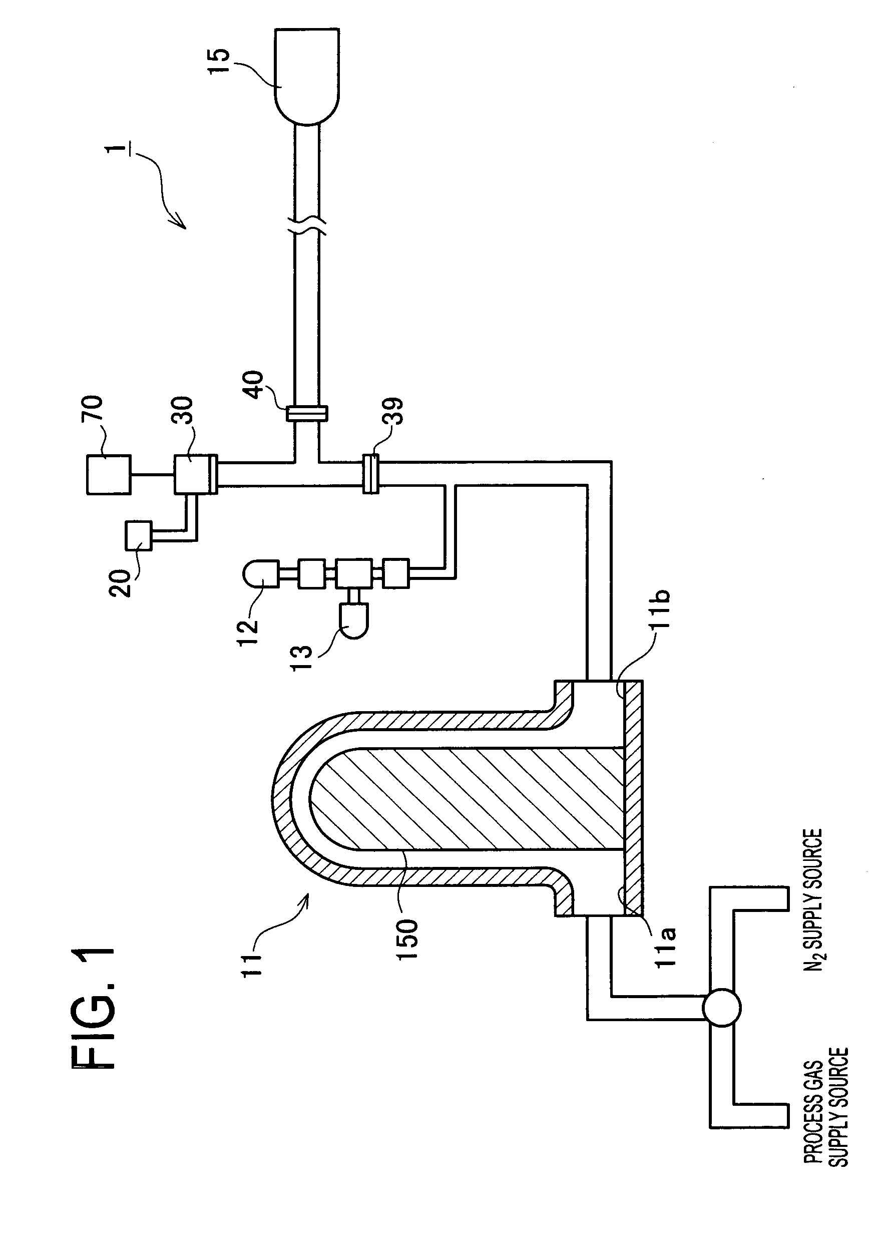
[0082]FIG. 1 is an explanatory view showing a configuration of a vacuum pressure control system 1 in the present embodiment. This system 1 is arranged to supply and discharge a process gas and a purge gas alternately in and out of a vacuum chamber 1 in which a wafer 150 is set, for surface treatment on the wafer 150 in a semiconductor manufacturing process.

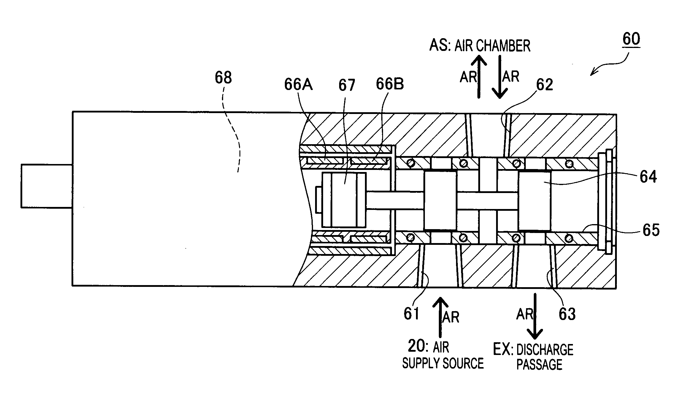
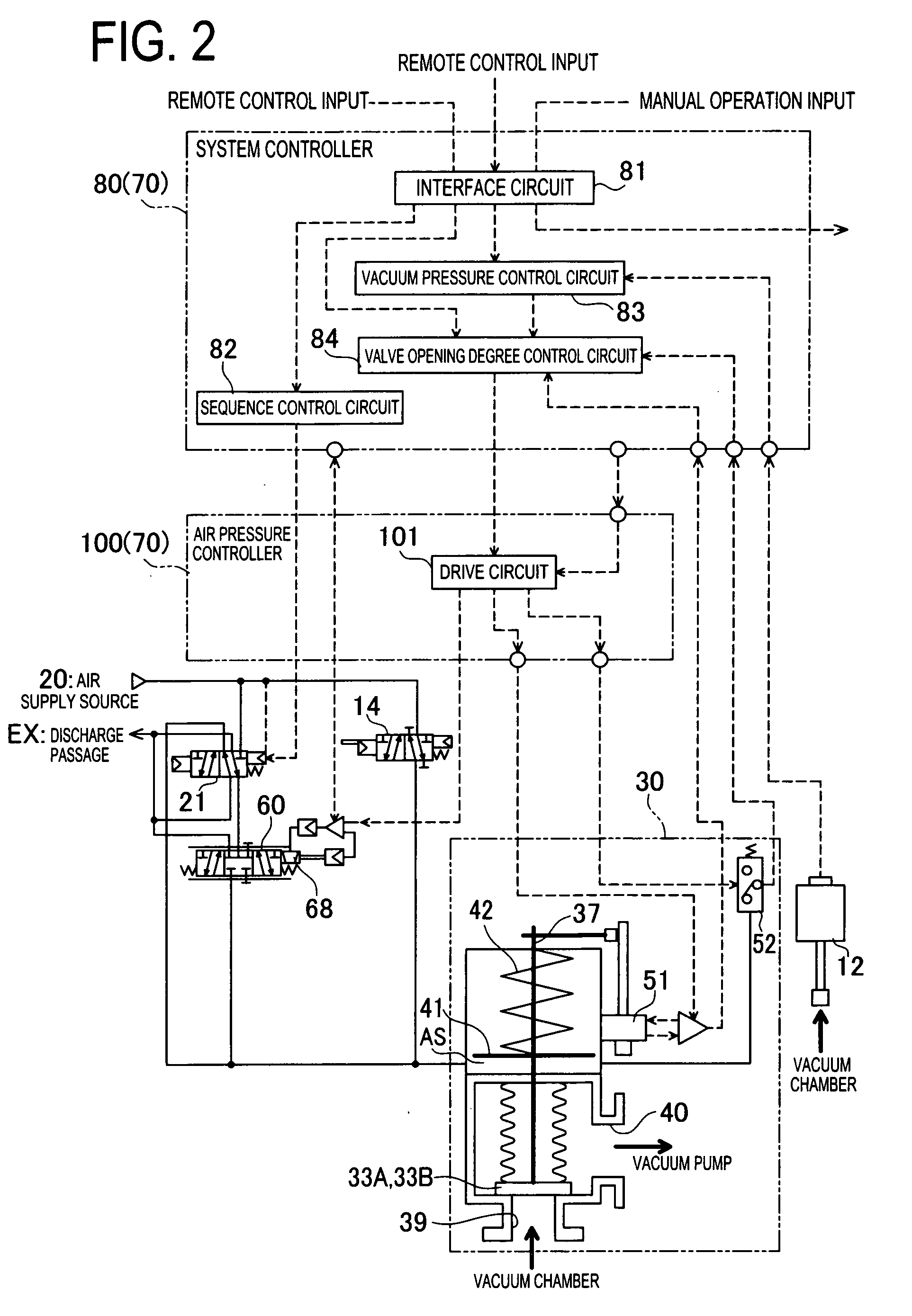
[0083]The vacuum pressure control system 1 is constituted mainly by the vacuum chamber 11, a vacuum pump 15, an air supply source 20 (a fluid supply source), a vacuum open / close valve 30 (hereinafter, “open / close valve 30”), a servo valve 60 (see FIG. 5), a vacuum pressure control device 70 electrically connected to the open / close valve 30 and others, as shown in FIG. 1. In this system 1, driving air AR which is supplied from the air supply source 20 is ...


PUM


Abstract

A vacuum pressure control system includes a vacuum chamber, a vacuum pump for sucking gas from the vacuum chamber, a vacuum open/close valve for controlling vacuum pressure in the vacuum chamber by changing a opening degree by driving air supplied from an air supply source serving as a power source, a vacuum pressure control device for controlling the vacuum open/close valve, and a servo valve for controlling the opening degree of the vacuum open/close valve.

Description

BACKGROUND OF THE INVENTION[0001]1. Field of the Invention[0002]The present invention relates to a vacuum pressure control system for maintaining supplied gas at a correct vacuum pressure value in a vacuum container used in a semiconductor manufacturing process and also allowing rapid discharge of the gas out of the vacuum container.[0003]2. Description of Related Art[0004]In a semiconductor manufacturing process, heretofore, various vacuum pressure control systems have been proposed to alternately charge and discharge a process gas and a purge gas in and from a vacuum chamber in which a wafer is disposed. Some of the vacuum pressure control systems are arranged to control flow passage and shutoff of the gasses with an electromagnetic valve and an electro-pneumatic proportion valve in sealing or discharging the gas supplied into the vacuum chamber (see JP9(1997)-72458A).[0005]This vacuum pressure control system disclosed in JP'458A is briefly explained below referring to FIGS. 12 to...

Claims


Application Information

Patent Timeline
IPC IPC(8): F16K31/124
CPCF16K31/0613Y10T137/7762H01L21/68742F15B5/00F16K51/02
Inventor WATANABE, MASAYUKIMIYAHARA, MAKOTOUMEZAWA, SHUNSUKE
Owner CKD
Why Eureka
Try Eureka