
Hydrogen Generator

a generator and hydrogen technology, applied in the field of hydrogen generators, can solve the problems of increasing dependence on imported petroleum, increasing the cost of hydrocarbon fuels, so as to and reduce the risk of explosion

Inactive Publication Date: 2008-12-11
MESA ENERGY
View PDF18 Cites 64 Cited by
  • Summary
  • Abstract
  • Description
  • Claims
  • Application Information

AI Technical Summary

Benefits of technology

[0018]Another notable advantage of the invention is that it minimizes the risk of explosion. It does this by limiting hydrogen and oxygen production according to engine demand, and also by preventing these gases from accumulating under pressure. Another advantage is the extended service life realized by shifting reactor duty cycles. Another advantage is the simplicity of the design. Thus, hydrogen generation according to this invention is practical, safe, and requires little maintenance.
is that it minimizes the risk of explosion. It does this by limiting hydrogen and oxygen production according to engine demand, and also by preventing these gases from accumulating under pressure. Another advantage is the extended service life realized by shifting reactor duty cycles. Another advantage is the simplicity of the design. Thus, hydrogen generation according to this invention is practical, safe, and requires little maintenance.

Problems solved by technology

The costs and the political consequences are enormous.
However, the cost of hydrocarbon fuels continues to rise and the dependence on imported petroleum continues to increase for most industrialized countries.
Carbon monoxide, unburned hydrocarbons, nitrogen oxides, and sulfur oxides are all harmful to the environment.
However, when engine emissions fail to meet an environmental standard, the consequences can be economically troublesome to a business, especially those that rely on large-scale engine operations.
The electrolytic hydrogen generators of Valdespino, Stowe, and Balan et al., as well as many other such generators that have been discussed or built, suffer from a variety of problems that have prevented them from achieving widespread use.
One problem is the risk of explosion inherent in any system that accumulates a volume of pressurized hydrogen gas.
Another problem is controlling the generator of hydrogen gas in response to engine demand.
Another problem is maintaining electrolyte level and temperature within desired limits during long term engine operation.
Another problem is developing a cost-effective system with uncomplicated controls.

Method used


Image

  • Hydrogen Generator
  • Hydrogen Generator
  • Hydrogen Generator

Examples


Embodiment Construction

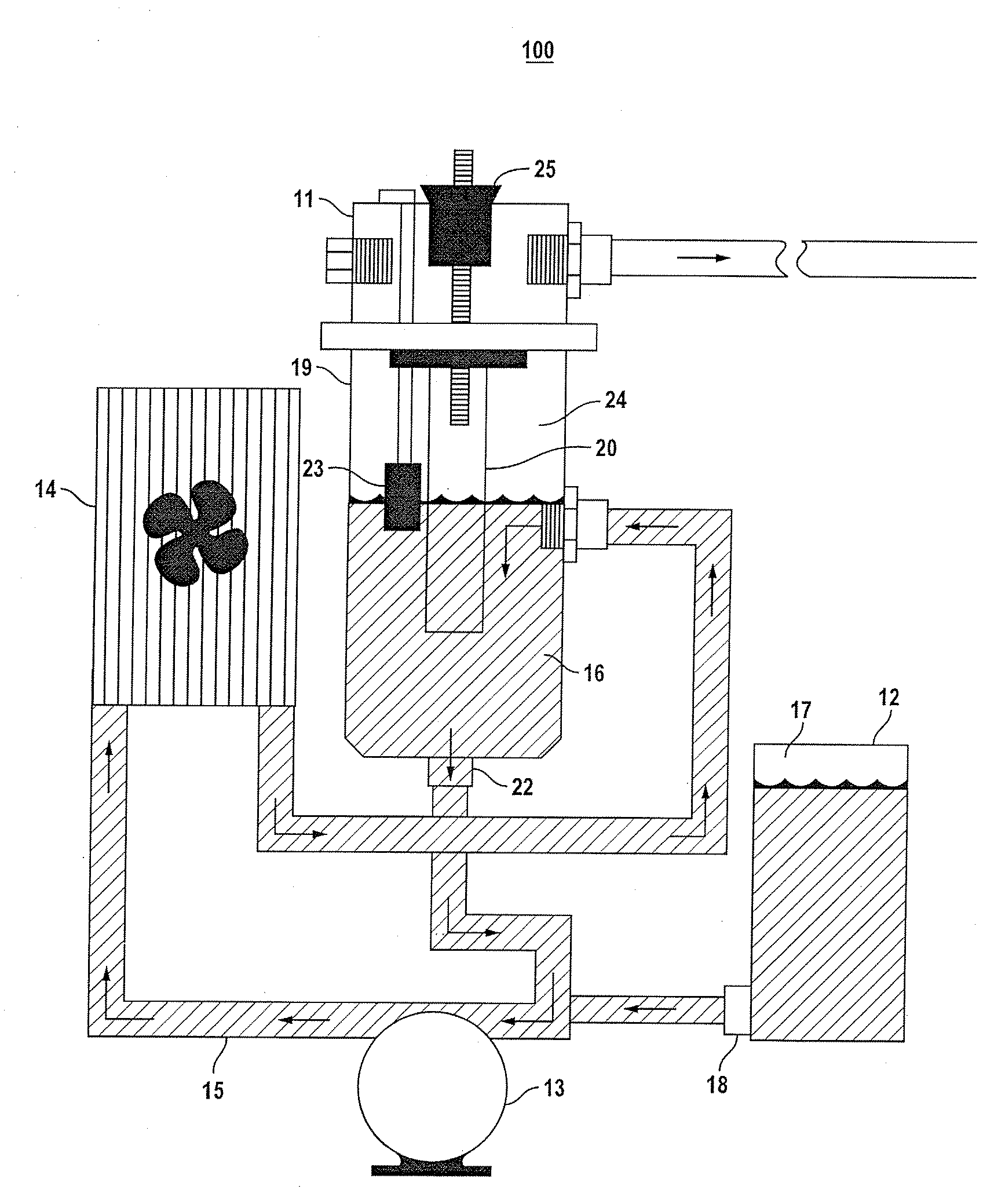
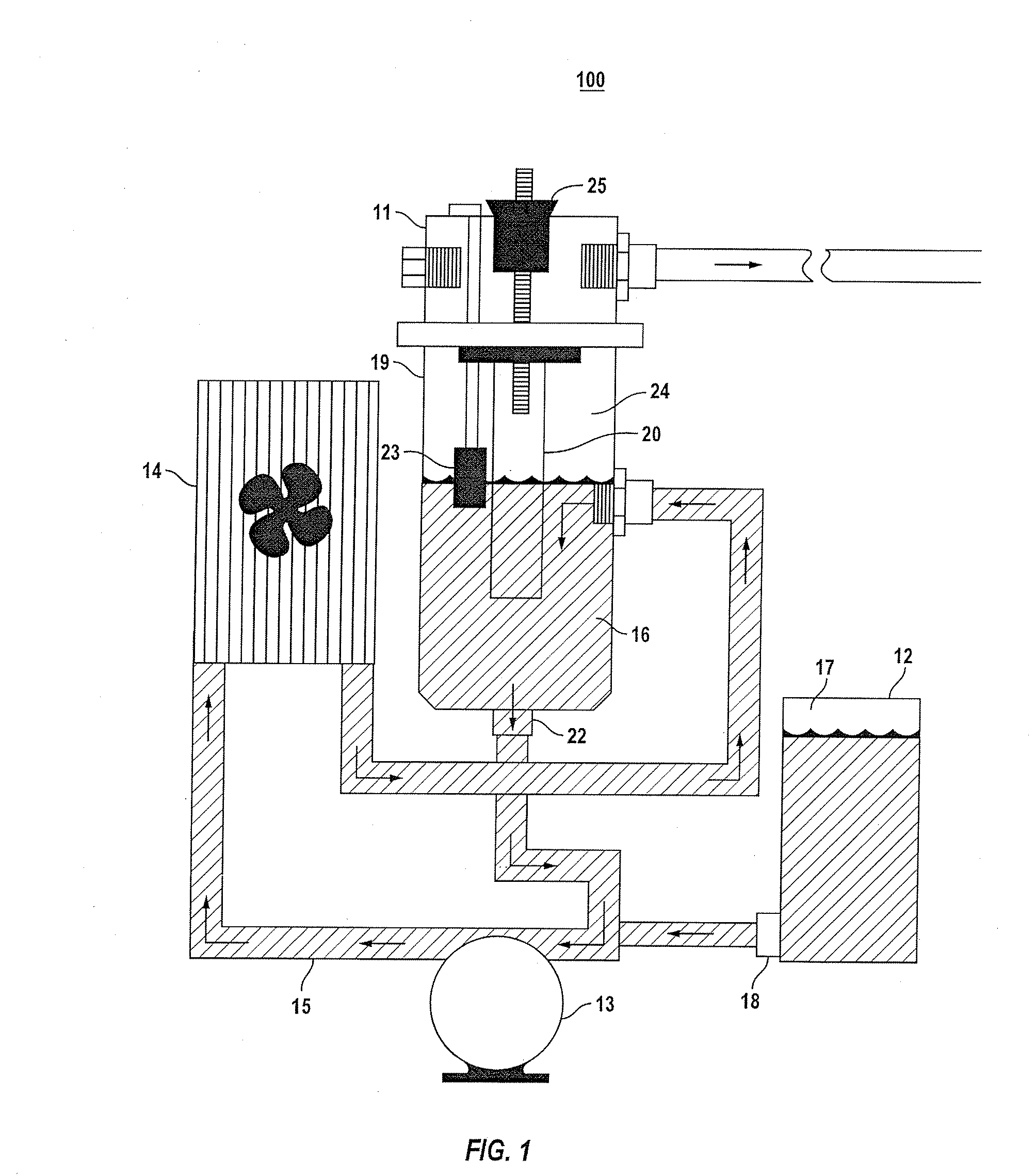
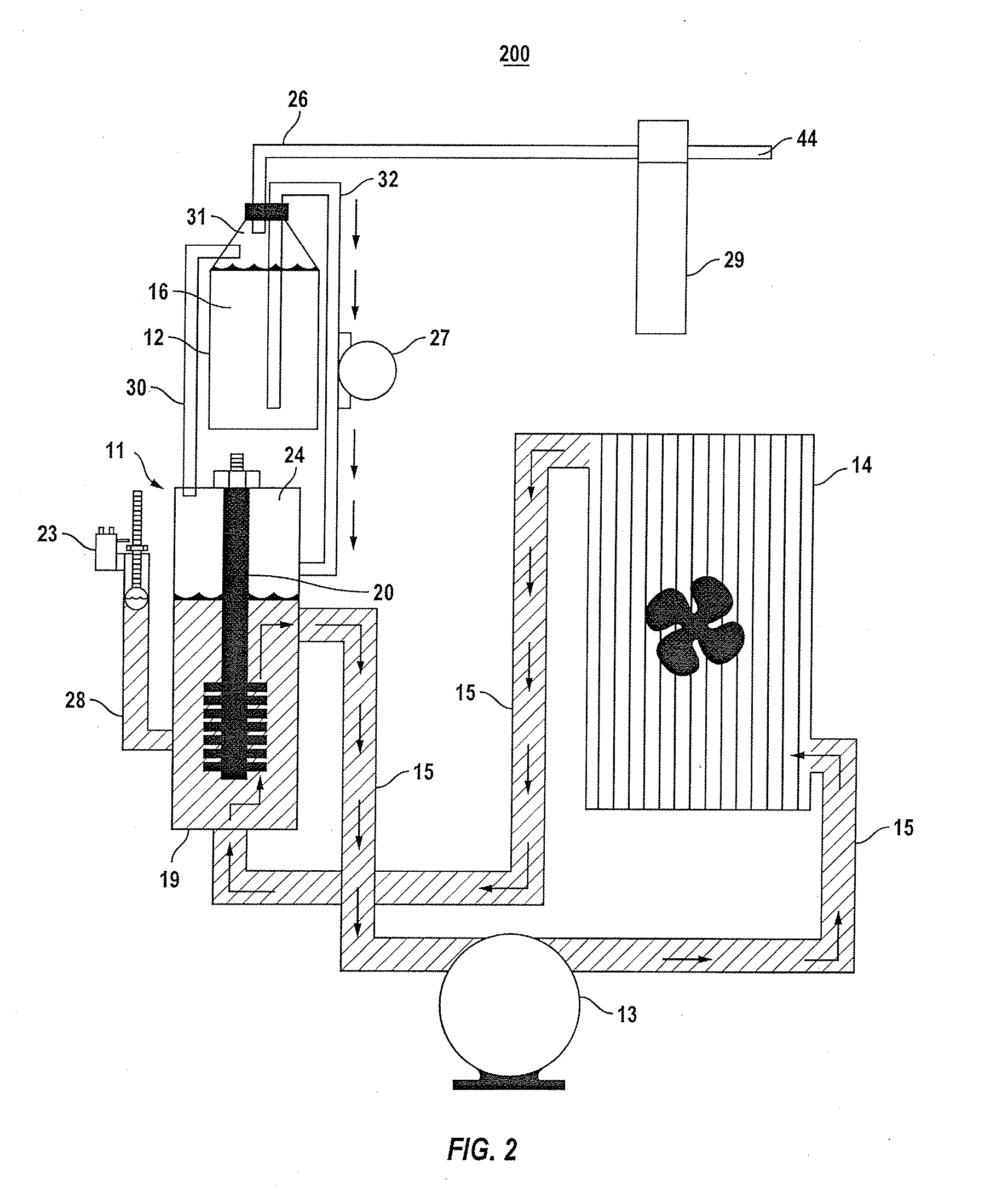
[0031]FIG. 1 illustrates a system 100 according to the present invention. In this embodiment, the system comprises an electrolytic reactor 11, a refillable reservoir 12, a pump 13, a heat exchanger 14, and conduit 15 connecting the foregoing components as shown. System 100 produces hydrogen and oxygen by electrolysis of water within reactor 11. The hydrogen and oxygen are produced to supplement hydrocarbon fuel burned in a combustion chamber, such as a wood or oil burning stove, a coal furnace, or cylinders of an internal combustion engine. Electrical power for energizing reactor 11 may originate from an independent source, or it may be derived from the electrical system of an engine. To simplify the disclosure, no combustion chambers or engines are shown in any of the figures.

[0032]Refillable reservoir 12 is configured to hold up to about two gallons of ionized water, although this volume may vary according to the particular application. Reservoir 12 may be constructed of a lightwe...


PUM


Abstract

A generator produces variable output of hydrogen and oxygen from electrolysis of water as a fuel supplement for combustion of hydrocarbon fuel. The generator includes an electrolytic reactor having a sealed cathode chamber partially filled with an electrolyte solution, and an anode immersed within the solution and electrically isolated from the chamber. A level sensor and reservoir maintain solution levels in one or more reactors configured in electrolyte communication. A source of electrical power energizes reactors responsive to changing combustion demand. A cooling system cools the reactors to allow the generator to operate at high amperage. An optional controller shifts reactor duty cycles to equalize reactor service over time. Gases produced in reactor air space above solution level are drawn or pumped to a combustion chamber to combine with hydrocarbon fuel and air. The combination results in greater combustion efficiency and reduces harmful emissions.

Description

BACKGROUND OF THE INVENTION[0001]1. Field of the Invention[0002]The present invention relates to hydrogen generators for improving the efficiency of hydrocarbon fuel combustion. More specifically, the invention relates to hydrogen generators used with internal combustion engines to reduce harmful emissions from the internal combustion engines.[0003]2. Description of Related Art[0004]An internal combustion engine produces power by burning a fuel within the combustion chambers of the engine. The fuel is mixed with air (which contains about twenty percent oxygen) and fed into the combustion chambers. The burning produces explosion and gases that move one or more pistons or rotors. The moving pistons or rotors are connected to an output shaft. Internal combustion engines are used to power automobiles, trucks, boats, tools, generators, and many other devices. The three main types of internal combustion engines are the conventional piston engine, the rotary engine, and the diesel engine.[...

Claims


Application Information

Patent Timeline
IPC IPC(8): C25B15/02
CPCC01B3/32C01B13/0207C01B2203/0216C01B2203/1223C25B1/04C25B15/02C25B15/08F02B47/06F02M21/06F02M25/12F02M27/04Y02E60/366Y02T10/121Y02T10/32F02M21/0206F02M21/0227F02D19/022Y02E60/36Y02T10/12Y02T10/30
Inventor BOYLE, ARNOLD D.
Owner MESA ENERGY
Learn More