Multiband antenna system and methods

a multi-band antenna and antenna technology, applied in the direction of resonance antennas, independent non-interacting antenna combinations, radiating element structural forms, etc., can solve the problems of insufficient characteristics, more demanding antenna design tasks, and insufficient antennas of the kind described, so as to achieve small antenna size, small bandwidth, and high permittivity

Inactive Publication Date: 2008-12-11
CANTOR FITZGERALD SECURITIES
View PDF65 Cites 31 Cited by
  • Summary
  • Abstract
  • Description
  • Claims
  • Application Information

AI Technical Summary

Benefits of technology

[0012]The exemplary embodiment of the invention has the advantage that the size of the antennas can be made small. This is due to that when there is a plurality of antennas, a relatively small bandwidth is sufficient for an individual antenna. When the bandwidth is small, a material with higher permittivity can be chosen for the antenna than for an antenna having a wider band, in which case the antenna dimensions can be made correspondingly smaller. In addition, the invention has the advantage that a good matching is achieved on the whole width of the band of each radio system. This is due to that the matching of a separate antenna having a relatively narrow band is easier to arrange than the matching of a combined multiband antenna. The exemplary embodiment of the invention further has the advantage that the number of the necessary antennas can be decreased without compromising the matching. For example, when the time division duplex is used, the separate transmitting and receiving antennas can be replaced with an antenna equipped with said adjusting circuit. The operating band of this antenna is displaced from the transmitting band to the receiving band and vice versa, as needed. The matching and also the efficiency are in part improved by the fact that in a decentralized system the antennas can each be located in a place which is advantageous with regard to its function. The exemplary embodiment of the invention further has the advantage that the isolation between the antennas is good. This is due to the sensible decentralization of the antennas and the fact that a substrate with a relatively high permittivity collapses the near field of the antenna.

Problems solved by technology

This makes the design of the antenna a more demanding task compared to an external antenna.
Extra difficulties in the design is caused when the radio device has to function in a plurality of frequency ranges, the more the wider these ranges or one of them are.
The antennas of the kind described above have the drawback that their characteristics are insufficient when the number of radio systems in accordance with which the radio device must function increases.
The insufficiency appears e.g. from that the matching of the antenna is poor in the band used by one of the radio systems or in a part of at least one of such bands.
In addition, it is difficult to make sufficient isolation between the antenna parts corresponding to different bands.
The drawbacks are emphasized when the antenna size has to be compromised because of the lack of space.

Method used


Image

  • Multiband antenna system and methods
  • Multiband antenna system and methods
  • Multiband antenna system and methods

Examples


Embodiment Construction

[0049]Reference is now made to the drawings wherein like numerals refer to like parts throughout.

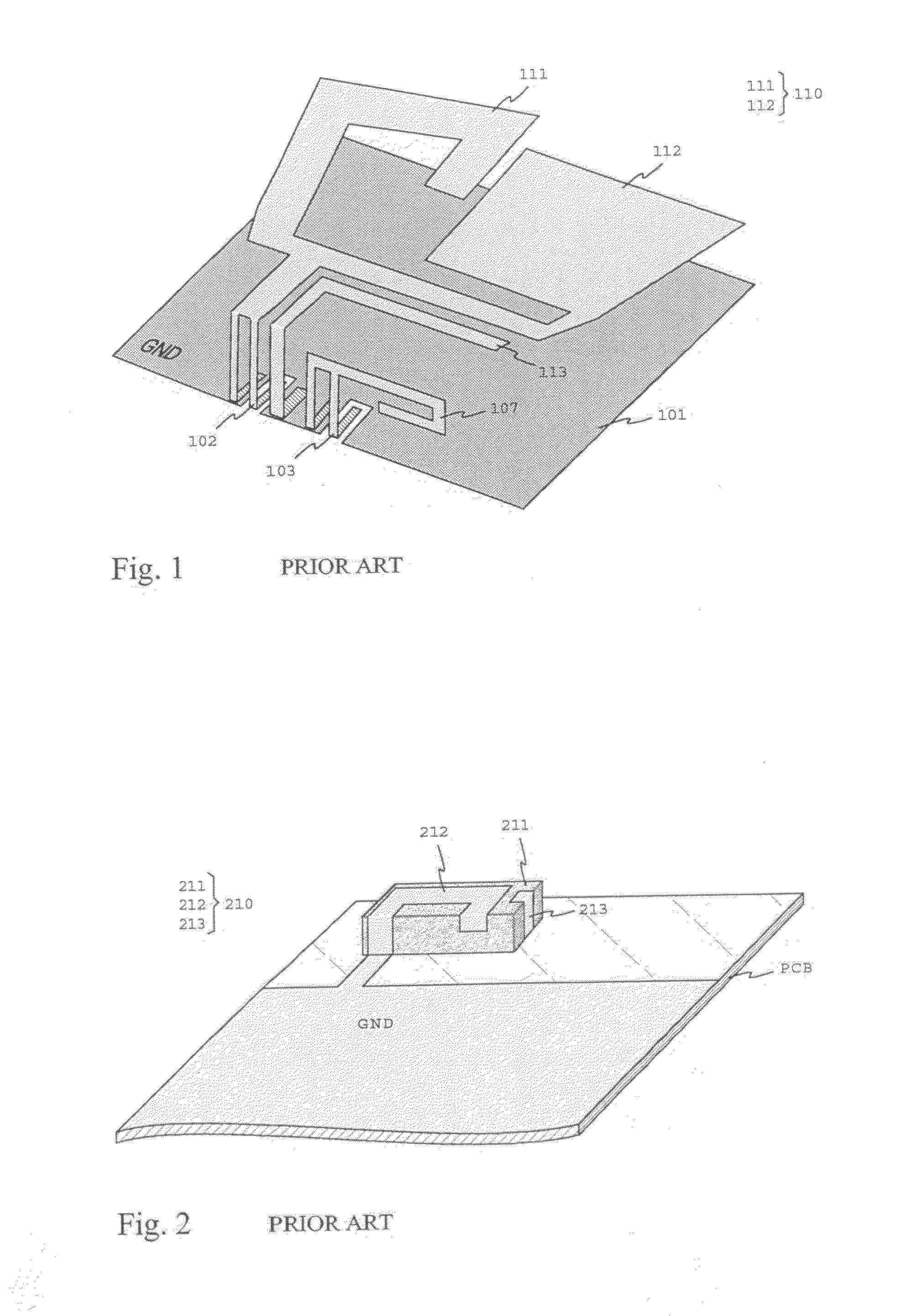
[0050]FIGS. 1 and 2 were already described in connection with the prior art.

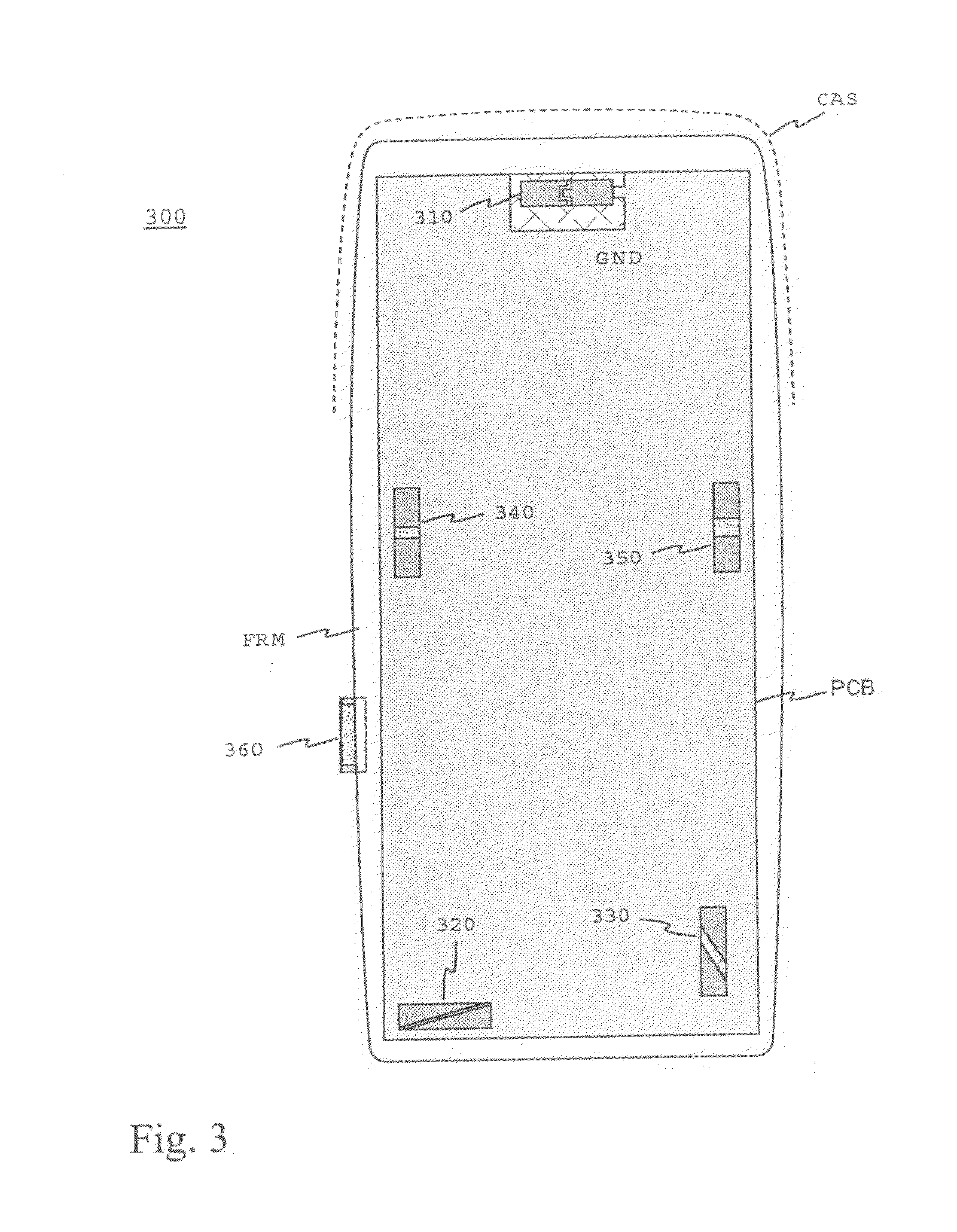
[0051]FIG. 3 shows an example of an antenna system according to the invention as a layout drawing. There is a radio device 300 with a circuit board PCB, plastic frame FRM and casing CAS in the drawing. A large part of the surface of the circuit board on the side visible in the drawing consists of a conductive ground plane GND. In this example the antenna system includes six antennas. Each one of these comprises an elongated antenna component with a ceramic substrate and two radiating elements. The ground plane around the antenna component is also considered to be a part of the antenna here. In this example, the radiating elements of each antenna component are of the same size so that they resonate on the same, relatively narrow frequency range. The feed conductor of an antenna is connected to one element, and the...


PUM


Abstract

An antenna system internal to a radio device, the system comprising separate antennas and having separate operating bands. The system is implemented as decentralized in a way that each antenna is typically based on a small-sized chip component (310; 320; 330; 340; 350; 360; 610), which are located at suitable places on the circuit board (PCB) and possibly on also another internal surface in the device. The chip component comprises a ceramic substrate and at least one radiating element. The operating band of an individual antenna covers e.g. the frequency range used by a radio system or only the transmitting or receiving band in that range. At least one antenna is connected to an adjusting circuit with a switch, by which the antenna's operating band can be displaced in a desired way. In this case the operating band covers at a time a part of the frequency range used by one or two radio systems. The antennas can be made small-sized, because a relatively small bandwidth is sufficient for an individual antenna, when there is a plurality of antennas. When the bandwidth is small, a material with higher permittivity can be chosen for the antenna than for an antenna having a wider band, in which case the antenna dimensions can be made correspondingly smaller. In addition, a good matching of the antenna is achieved on the whole width of each radio system, because the matching of a separate antenna having a relatively narrow band is easier to arrange than that of a combined multiband antenna.

Description

PRIORITY AND RELATED APPLICATIONS[0001]This application claims priority to International PCT Application No. PCT / FI2006 / 050402 having an international filing date of Sep. 20, 2006, which claims priority to Finland Patent Application No. 20055527 filed Oct. 3, 2005, as well as Finland Patent Application No. 20055554 filed Oct. 14, 2005, each of the foregoing incorporated herein by reference in its entirety. This application is related to co-owned and co-pending U.S. patent application Ser. No. 12 / ______ filed contemporaneously herewith and entitled “Multiband Antenna System And Methods” (Attorney docket No. LKP.014A / OP101722), Ser. No. 12 / 009,009 filed Jan. 15, 2008 and entitled “Dual Antenna Apparatus And Methods”, Ser. No. 11 / 544,173 filed Oct. 5, 2006 and entitled “Multi-Band Antenna With a Common Resonant Feed Structure and Methods”, and co-owned and co-pending U.S. patent application Ser. No. 11 / 603,511 filed Nov. 22, 2006 and entitled “Multiband Antenna Apparatus and Methods”, ...

Claims


Application Information

Patent Timeline
Patent Type & Authority Applications(United States)
IPC IPC(8): H01Q3/24H01Q1/00H01QH01Q1/24H01Q5/00H01Q5/378H01Q9/04H01Q21/28
CPCH01Q1/243H01Q9/0421H01Q5/378H01Q21/28H01Q9/145H01Q1/38H01Q5/00H01Q21/30H01Q1/24
Inventor MILOSAVLJEVIC, ZLATOLJUBNISSINEN, PERTTILESKELA, ANTTIANNAMAA, PETTERI
Owner CANTOR FITZGERALD SECURITIES
Why Eureka
Try Eureka