

Low Temperature Thermal Conductive Inks
a thermal conductive ink and low temperature technology, applied in the field of printed electronics, can solve the problems of high volume and low cost printed electronics devices, waste of excess material consumed in the first step, and remains a relatively expensive metal
- Summary
- Abstract
- Description
- Claims
- Application Information
AI Technical Summary
Benefits of technology
Problems solved by technology
Method used
Image

Examples
working examples
Example 1
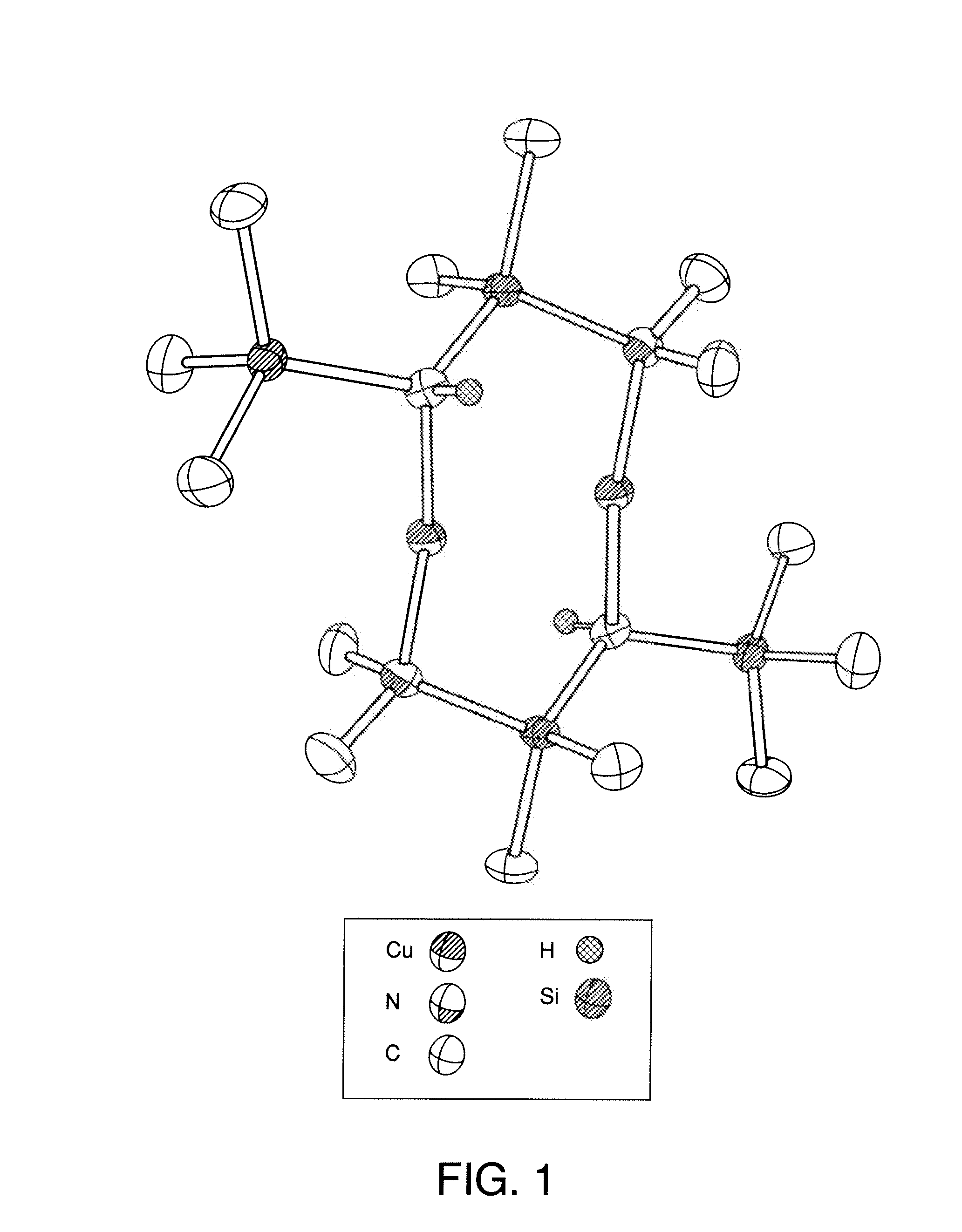
Synthesis of Cu4MPA
[0086]One equivalent of G2 complex was mixed with 4.4 equivalent of dry deoxygenated 4-methyl-2-pentanol and stirred for 6 days at 45° C. under a nitrogen atmosphere. During this period, the mixture became a clear yellow liquid with a trace of copper particulates. These were filtered off using a 0.1 micron filter. The resulting solution was connected to a distillation system, then heated to 40° C. under dynamic vacuum with the receiving vessel cooled with liquid nitrogen. 12 hrs later, all of the G2OR by-product had transferred into the receiving vessel leaving the Cu4MPA as a clear golden yellow oil.
[0087]The above process was applied to the appropriate alcohols listed in Table 2 to yield the copper inks Cu4MPA, Cu2HXA, Cu3PA, CuDMP, Cu5MH, Cu2NONA, Cu2OCTA, Cu2PA, Cu2MPA and Cu2MBA.
example 2
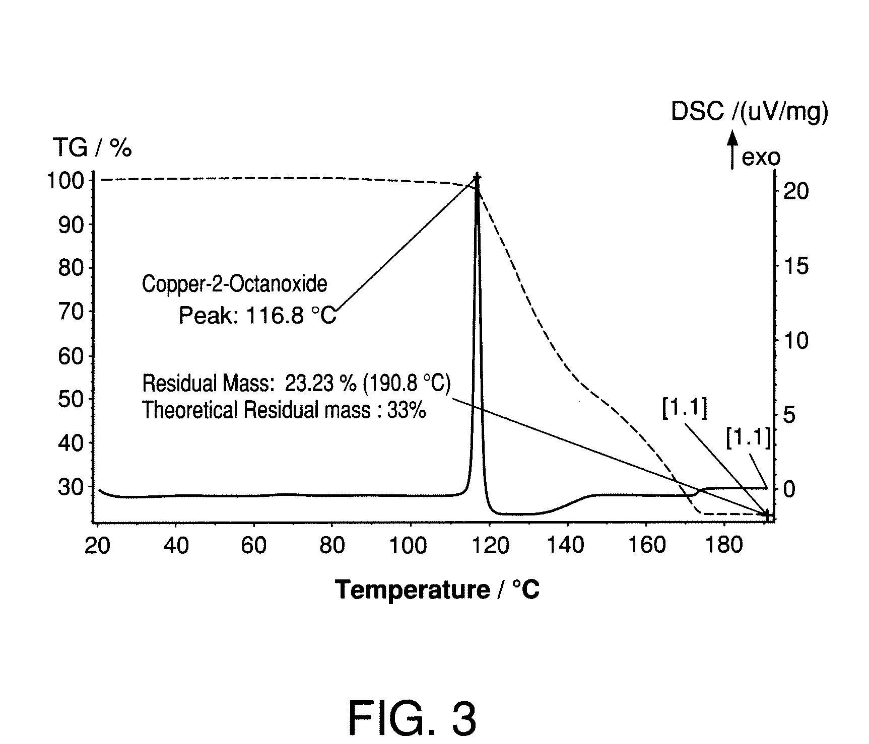
Synthesis of Cu2OCTA
[0088]1.0 g of copper t-butoxide was dissolved in 20 ml of dry deoxygenated tetrahydrofuran under nitrogen at room temperature. To this was added 1.05 g of dry 2-octanol and the mixture stirred for 2 hours. The volatiles were then removed to yield 1.23 g CuOCTA (91.1%)
example 3
Synthesis of Cu2NONA
[0089]1.0 g of copper t-butoxide was dissolved in 20 ml of dry deoxygenated tetrahydrofuran under nitrogen at room temperature. To this was added 1.11 g of dry 2-nonanol and the mixture stirred for 2 hours. The volatiles were then removed to yield 1.20 g CuNONA (82.7%)
PUM
| Property | Measurement | Unit |
|---|---|---|
| Temperature | aaaaa | aaaaa |
| Frequency | aaaaa | aaaaa |
| Temperature | aaaaa | aaaaa |
Abstract
Description
Claims
Application Information