Fuel cell separator plate surface treatment by laser ablation

a technology of laser ablation and separator plate, which is applied in the field of polymeric separator plate, can solve the problems of low electrical conductivity of polymeric resin material, prone to breakage of brittle separator plate, and formation of thin layer of polymeric resin on the outside of the formed plate, so as to maintain proper strength and corrosion reduce the contact resistance of the plate, and improve the effect of electrical conductivity

Inactive Publication Date: 2008-12-11
GM GLOBAL TECH OPERATIONS LLC
View PDF5 Cites 22 Cited by
  • Summary
  • Abstract
  • Description
  • Claims
  • Application Information

AI Technical Summary

Benefits of technology

[0010]The present invention provides a method for forming a separator plate with a protective outer layer and using laser ablation to selectively remove the outer layer for reducing the contact resistance of the plate in those areas while possessing the beneficial properties of the protective outer layer in other areas of the plate. The separator plate can thus be manufactured with a polymeric material content sufficient to maintain proper strength and corrosion resistance of the plate, while the use of laser ablation improves electrical conductivity as compared with the prior art methods of producing these separator plates. Alternatively, the plate can be fabricated from a metal having an outer oxide layer. The laser ablation process also leaves a relatively smooth surface on the metal separator plate free of the defects typical of grinding or sanding.

Problems solved by technology

However, this generally results in a brittle separator plate prone to breaking during operation or handling of the fuel cell.
Still, the compression molding process commonly used to form separator plates tends to cause the formation of a thin layer of polymeric resin on the outside of the formed plate.
This thin, outer layer of polymeric resin material is low in electrical conductivity, and therefore tends to further increase the contact resistance of the separator plate.
There are still disadvantages to removing this outer layer of material through mechanical processes.
These processes are relatively harsh operations for such delicate plates, and can easily result in breakage of the plates which are subjected to them.
Even when performed properly, these operations tend to leave the plate with grooves or scratches and compromise the integrity of the conductive carbon particles that are left on the resulting surface.
These carbon particles, which are important to maintaining the electrical conductivity of the plate, will tend to become loose and rub off of the plate as a result of grinding or sanding, leaving small voids on the surface of the plate.
The scratches, grooves, and voids effectively reduce the electrical conductivity of the plate, and thus decrease the overall efficiency of the fuel cell stack.
However, this oxide layer tends to increase the contact resistance of the plate.

Method used


Image

  • Fuel cell separator plate surface treatment by laser ablation
  • Fuel cell separator plate surface treatment by laser ablation
  • Fuel cell separator plate surface treatment by laser ablation

Examples


Embodiment Construction

[0027]The following description of the preferred embodiment is merely exemplary in nature and is in no way intended to limit the invention, its application, or uses.

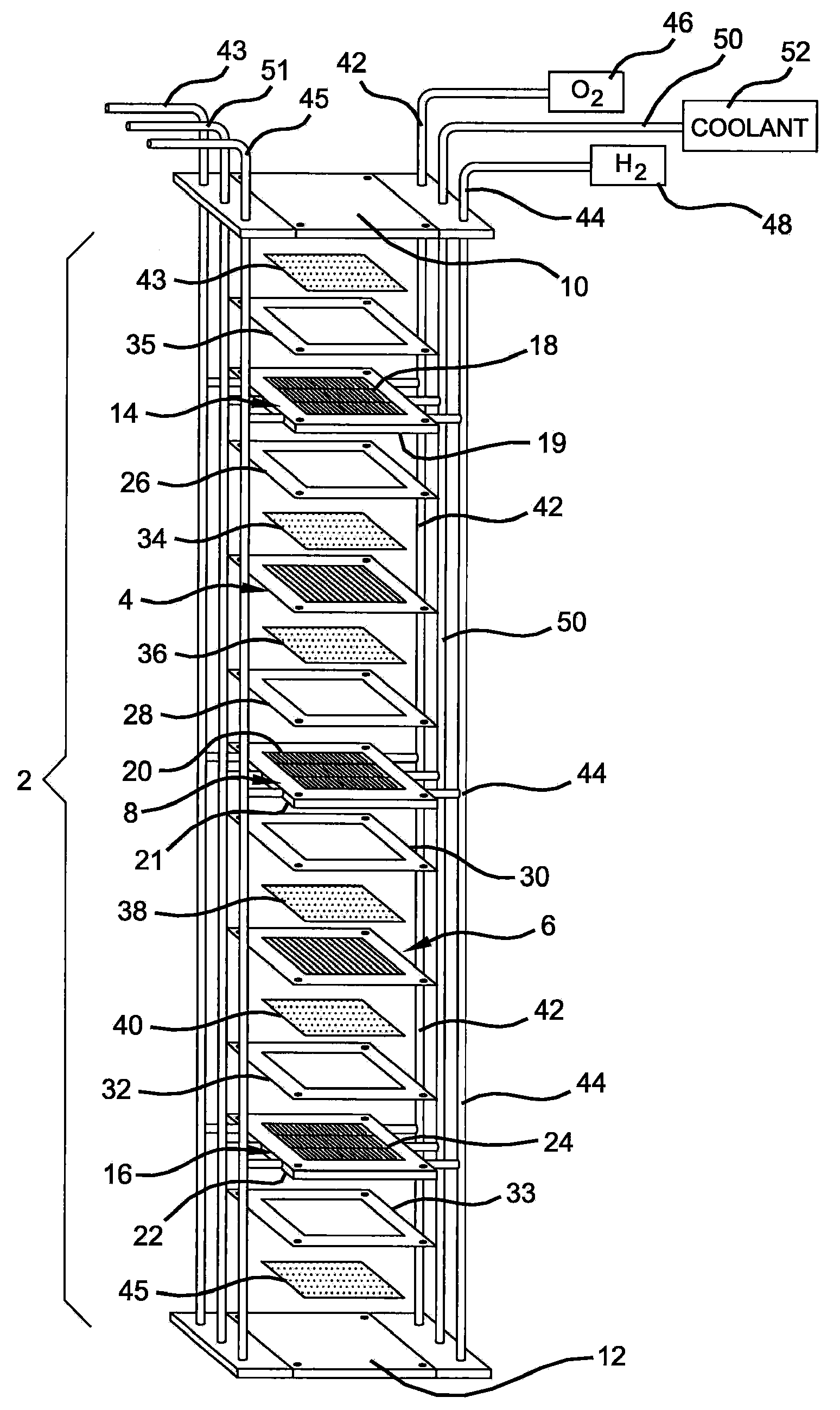
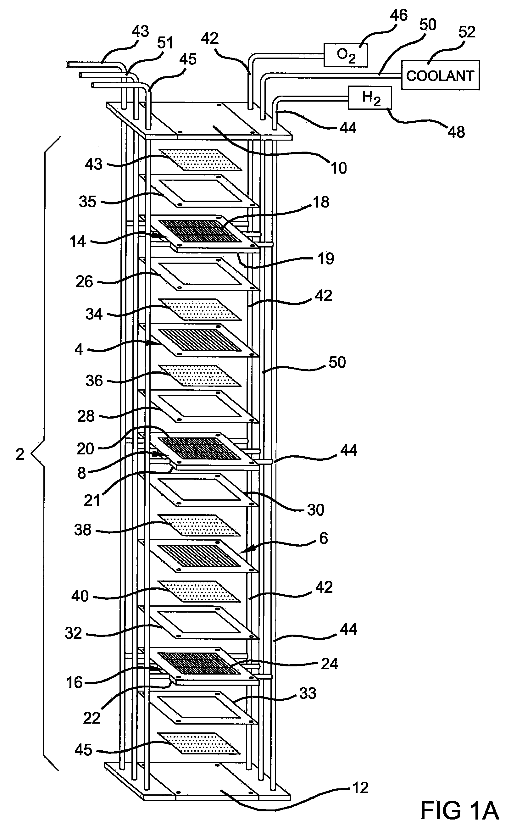
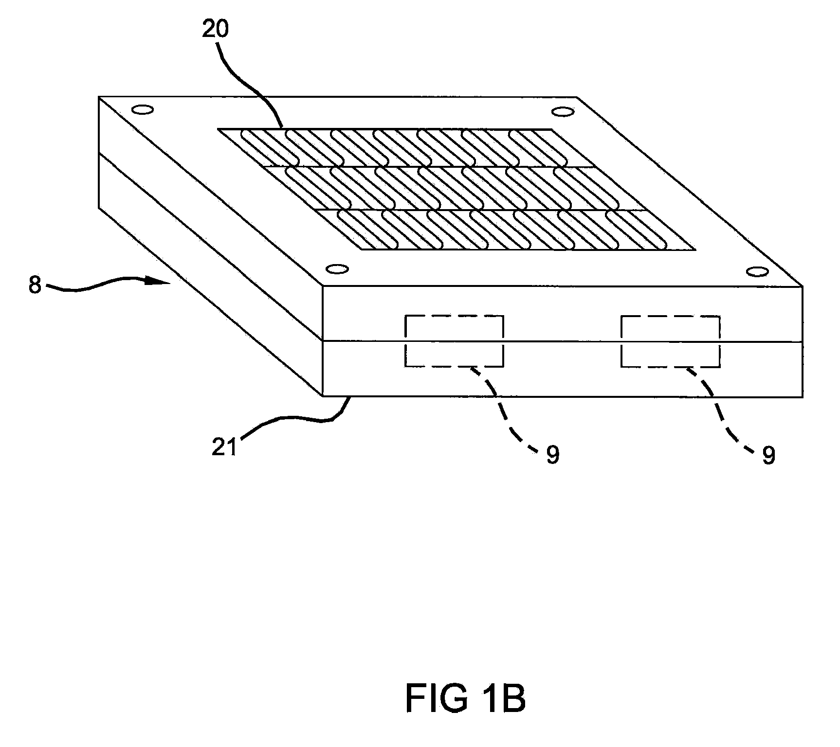
[0028]A method of forming a composite separator plate for use in an electrochemical fuel cell stack is provided in which the plate is formed by compression molding, or any of a variety of alternative methods known in the art, and then using laser ablation to remove a thin outer layer from the plate. The composite separator plate has a body including at least one polymeric material and at least one electrically conductive material. A series of flow channels are formed in a generally smooth surface with conductive particles intact at the surface of anode and cathode composite molded halves that are then bonded together by using a conductive adhesive at the coolant interface to form a bipolar plate. Alternatively, the plate is formed by a metal forming operation and a subsequent optional coating operation. The anode and cat...


PUM

PropertyMeasurementUnit
step sizeaaaaaaaaaa
contact angleaaaaaaaaaa
electrically conductiveaaaaaaaaaa

Abstract

A composite separator plate for use in an electrochemical fuel cell as well as a method of forming same is disclosed. The plate may be formed of polymeric material and electrically conductive material having a non-conductive polymeric outer layer by compression molding, or alternately of a metallic material having an outer metal oxide layer. Contact regions of the plate surface are subsequently ablated with a laser to remove the outer layer of material from the plate. The removal of the outer layer reduces the contact resistance of the plate when used in an electrochemical fuel cell stack, while offering adequate strength and corrosion resistance for the fuel cell stack environment.

Description

FIELD OF THE INVENTION[0001]The present invention relates to Proton Exchange Membrane (PEM) fuel cells, and, more particularly, to polymeric separator plates and a method for making the same.BACKGROUND OF THE INVENTION[0002]Fuel cells have been proposed as a power source of the future for automobiles and other industrial applications. One known fuel cell design is the PEM fuel cell that includes a “membrane-electrode assembly” comprising a thin, solid polymer membrane-electrolyte having an anode on one face of the membrane-electrolyte and a cathode on the opposite face of the membrane-electrolyte. The anode and cathode typically comprise finely divided carbon particles, having very finely divided catalytic particles supported on the internal and external surfaces of the carbon particles, and proton conductive material intermingled with the catalytic and carbon particles.[0003]The membrane-electrode assembly is sandwiched between a pair of electrically conductive contact elements whi...

Claims


Application Information

Patent Timeline
Patent Type & Authority Applications(United States)
IPC IPC(8): H01M2/16H01M2/14
CPCH01M8/0206H01M8/0215Y10T29/49115H01M8/0247Y02E60/50H01M8/0228
Inventor SMILJANICH, DAVID A.DATTA, REENA L.
Owner GM GLOBAL TECH OPERATIONS LLC
Why Eureka
Try Eureka