Hydrocarbon separation from air using membrane separators in recirculation tube

a technology of membrane separator and hydrocarbon separation tube, which is applied in the direction of combustion air/fuel-air treatment, machines/engines, transportation and packaging, etc., can solve the problems of increasing the complexity and cost of the evaporative emissions system, requiring additional space considerations, and using additional canisters. the effect of reducing the load on the canister system, optimizing the overall evaporative emissions system, and efficient configuration

Inactive Publication Date: 2008-12-18
FLUID ROUTING SOLUTIONS
View PDF52 Cites 10 Cited by
  • Summary
  • Abstract
  • Description
  • Claims
  • Application Information

AI Technical Summary

Benefits of technology

[0008]By installing the membrane in the recirculation tube, the membrane separates a substantial amount of the hydrocarbon fuel from air at the fuel tank and recirculates the hydrocarbon fuel to the fuel tank, thereby reducing the load on the canister system so that the overall evaporative emissions system can be optimized by allowing the use of smaller canisters which can be more efficiently configured and located in the emissions system.
[0009]The use of a separating membrane device as described herein allows the use of a larger diameter recirculation tube thereby allowing a larger volume of the air / fuel mixture to flow through the recirculation tube, thereby reducing the pressure inside the fuel tank leading to a lower flow rate through the carbon canister employed to adsorb the fuel vapors until they are purged and consumed in the internal combustion engine. The effective separation of hydrocarbons from air based on a membrane separator is achieved with an effective pressure drop across the membrane module. This can be achieved more effectively by having a gas compressor or a vacuum pump in the recirculation tube to create the desired pressure head. The improvement provided by the present invention is a much cleaner stream of air fed back into the filler pipe, a significantly more efficient reduction in the amount of fugitive emissions released to the atmosphere during fueling, and more smaller spatial requirements for the emissions canister which not only reduces material and labor costs, but allows greater flexibility with respect to the installation of such canisters.
[0010]The membrane useful in the present invention is characterized as a cellular fibular material having physical properties such as pore size, nominal flow path, membrane area and thickness favorable for the separation and trapping of fuel vapor molecules while allowing any air molecules present to flow freely therethrough. Membranes found to be effective in the present invention are available from Amersham Biosciences Membrane Separations Group, W. L. Gore & Associates.
[0015]Operating Temperature—Higher temperature increases molecular diffusivity and less size-discriminating gaps in the polymer matrix. Therefore, permeability increases and selectivity decreases.
[0016]In accordance with the invention, a module containing the membrane is positioned in a recirculating tube, which provides a closed loop vent from the fuel tank to the fuel filler pipe. During refueling, the displaced air / fuel vapor mixture from the fuel tank is passed to the membrane module where the membrane effectively separates the fuel vapor from the air / fuel mixture. Typically, the membrane is effective to prevent substantially all of the fuel vapor from passing therethrough while allowing substantially all of the air molecules to pass therethrough. The membrane allows the fuel vapor to return to the fuel tank while the air, separated from the air / fuel mixture, is allowed to freely pass to the filler pipe and eventually to the canister where any residual fuel vapor remaining in the air is adsorbed until it is consumed by the internal combustion engine during a purge step. More typically, the membrane prevents greater than about 80% of the fuel vapor molecules from passing through the membrane while allowing greater than about 95% of the air molecules to pass therethrough. Most typically, the membrane prevents greater than about 95% of the fuel vapor molecules from passing through the membrane while allowing greater than about 99% of the air molecules to pass therethrough. As in conventional canisters, the air substantially free of any fuel vapor is expelled through the canister to the atmosphere.
[0017]In one aspect of the invention, a gas compressor is placed between the fuel tank and the membrane module. In this design, the compressor is attached at the inlet of the membrane module, where it creates sufficient pressure head to provide a more effective separation of hydrocarbons from air wherein the hydrocarbons are returned to the fuel tank, while the clean air molecules are allowed to pass through the membrane.

Problems solved by technology

As a result of government mandates, automotive manufacturers are constantly being challenged to find better and more efficient ways to prevent or reduce the emissions of hydrocarbon fuel vapors and other pollutants into the atmosphere.
The use of additional canisters not only increase the complexity and cost of the evaporative emissions system, but also requires additional space considerations due to the limited space available in the region of the vehicle wherein a canister is installed.

Method used


Image

  • Hydrocarbon separation from air using membrane separators in recirculation tube
  • Hydrocarbon separation from air using membrane separators in recirculation tube

Examples


Embodiment Construction

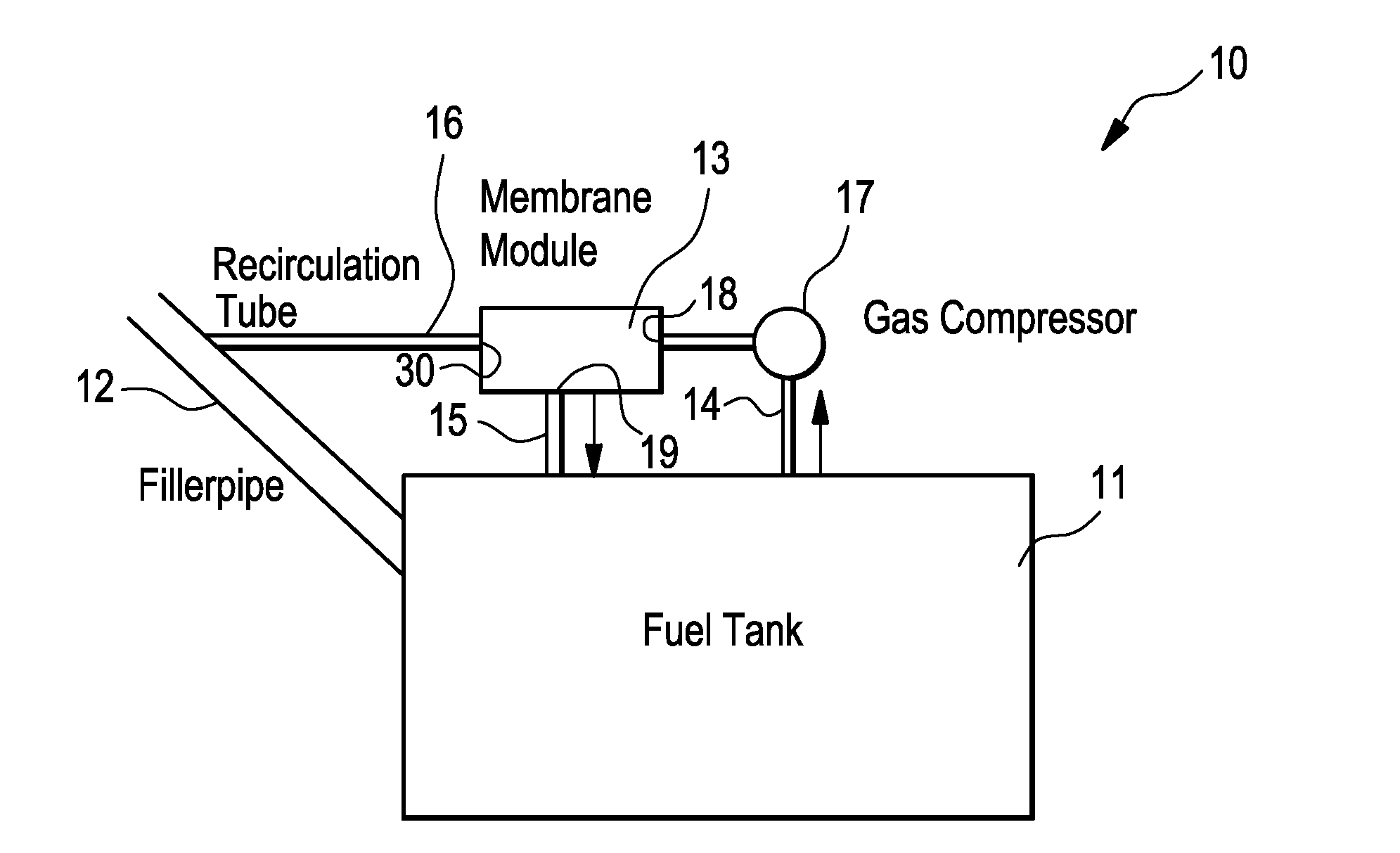
[0026]In accordance with the present invention, an effective separation system is employed for separating hydrocarbon fuel vapor molecules from air in an air / hydrocarbon fuel vapor mixture.

[0027]In one aspect of the invention, as illustrated in FIG. 1, the separation system 10 comprises a fuel tank 11 for receiving and storing fuel for powering an internal combustion engine. During the fueling stage where fuel from a fuel source, is pumped via a fuel nozzle into the fuel tank through filler pipe 12 via a fuel nozzle (not shown), pressure from a build-up of a vapor mixture of hydrocarbon fuel vapor and air causes the hydrocarbon fuel vapor / air mixture in the fuel tank 11 to flow from the fuel tank 11 to a membrane 32 disposed in a separation device 13 via port 18 through outlet line 14. The hydrocarbon fuel vapor is separated from the air / hydrocarbon fuel mixture in the membrane separation device 13 and returned to the fuel tank 11 via port 19 through hydrocarbon fuel return line 15....


PUM


Abstract

A tubular separation system for separating a mixture of hydrocarbons and air at a fuel tank in an automotive vehicle, comprises; a fuel tank containing hydrocarbon fuel and a mixture of hydrocarbon fuel vapor and air; a fuel filler pipe connected to the fuel tank for conveying hydrocarbon fuel from a source of hydrocarbon fuel into the fuel tank; a separation module comprising a membrane for separating the hydrocarbon vapor from air; a first tubular member between the fuel tank and the separation module for conveying the mixture of air and hydrocarbon fuel vapor from the fuel tank to the separation module; a second tubular member between the separation module and the fuel tank for conveying hydrocarbon fuel vapor, separated from the mixture of air and hydrocarbon fuel vapor, from the separation module to the fuel tank; and a third tubular member between the separation module and the fuel filler pipe for conveying air, separated from the mixture of air and hydrocarbon fuel vapor, from the separation module to the fuel filler pipe. A device that provides a pressure differential across said membrane is employed to facilitate the separation of air and hydrocarbon from the air/hydrocarbon mixture. The air containing any residual fuel vapor is directed to an emissions canister where the residual fuel vapor is adsorbed and eventually consumed by the internal combustion engine while the air is released to the atmosphere.

Description

BACKGROUND OF THE INVENTION[0001]The present invention relates to a fuel system for an internal combustion engine and, Particularly, to the separation of hydrocarbons from air in the separation tube at the fuel tank; and, most particularly, to a membrane separation system for providing a cleaner stream of air back into the fuel filler pipe.[0002]Evaporative emissions result from any one of several events which includes venting of fuel vapors from the fuel tank due to diurnal changes in ambient pressure and / or temperatures (known in the art as “diurnal” emissions), by refueling of the vehicle (known in the art as “refueling” emissions) or by vaporization of fuel by a hot engine and / or exhaust. Generally, the venting of fuel vapor from the fuel tank due to diurnal pressure and / or temperature (diurnal emission) and the escape of fuel vapor during refueling are responsible for a majority of the emissions.[0003]Environmental regulations imposed on the automotive industry, by the environm...

Claims


Application Information

Patent Timeline
Patent Type & Authority Applications(United States)
IPC IPC(8): F02M33/00
CPCB60K15/03504
Inventor BANERJEE, RAJADUMAS, JAMES T.FOSTER, RANDY C.GEPPER, DONALD L.
Owner FLUID ROUTING SOLUTIONS
Why Eureka
Try Eureka