Compact hydraulic accumulator

a compact, accumulator technology, applied in the direction of fluid couplings, couplings, functional valve types, etc., can solve the problems of poor reliability, high gas permeation rate of bladder accumulators, and limited spring types of accumulators with small fluid volumes, etc., to achieve mass production, easy serviceability, and light weight

Inactive Publication Date: 2008-12-18
NRG ENTERPRISES
View PDF32 Cites 91 Cited by
  • Summary
  • Abstract
  • Description
  • Claims
  • Application Information

AI Technical Summary

Benefits of technology

[0022]In concordance with the instant disclosure, a high pressure piston and sleeve accumulator design that is optimally efficient, extremely

Problems solved by technology

Spring type is typically limited to accumulators with small fluid volumes due to the size, cost, mass, and spring rates of the springs.
Bladder accumulators typically suffer from high gas permeation rates and poor reliability.
However, a principal shortcoming of this approach lies in the potential for the bellows to experience stresses and longitudinal disorientation that may rapidly lead to failure under a severe duty cycle, such as would be present in an automotive power system application.
However, the interface between the piston and the inner wall of the cylinder must be controlled tightly to ensure a good seal, and the degree of dimensional tolerance necessary to ensure a good seal may increase the cost of manufacturing.
As a result of the foregoing, standard piston accumulator vessels tend to be made of thick, high strength steel and are very heavy.
Standard piston accumulators have a much higher weight to energy storage ratio than either steel or composite bladder accumulators, which makes them undesirable for mobile vehicular applications (as such increased weight would, for example, reduce fuel economy for the vehicle).
Therefore, despite their potentially superior gas impermeability, piston accumulators are largely impractical for vehicular applications.
Sleeve movement would fatigue the rigid fixed end of the sleeve possibly leading to leakage due to cracking, distortion, or wear of the sealing gasket if one is present.
Like standard piston accumulators discussed above, these prior art piston-in-sleeve accumulators are unacceptably heavy for a hydraulic hybrid motor vehicle application or other application where accumulator weight is a significant issue.
As such, the Tovagliaro device would still remain undesirably heavy for a hydraulic hybrid motor vehicle application, and would also entail significantly greater manufacturing cost than desired

Method used


Image

  • Compact hydraulic accumulator
  • Compact hydraulic accumulator
  • Compact hydraulic accumulator

Examples


Embodiment Construction

[0034]The following description is merely exemplary in nature and is not intended to limit the present disclosure, application, or uses. It should also be understood that throughout the drawings, corresponding reference numerals indicate like or corresponding parts and features. In respect of the methods disclosed, the order of the steps presented is exemplary in nature, and thus, is not necessary or critical.

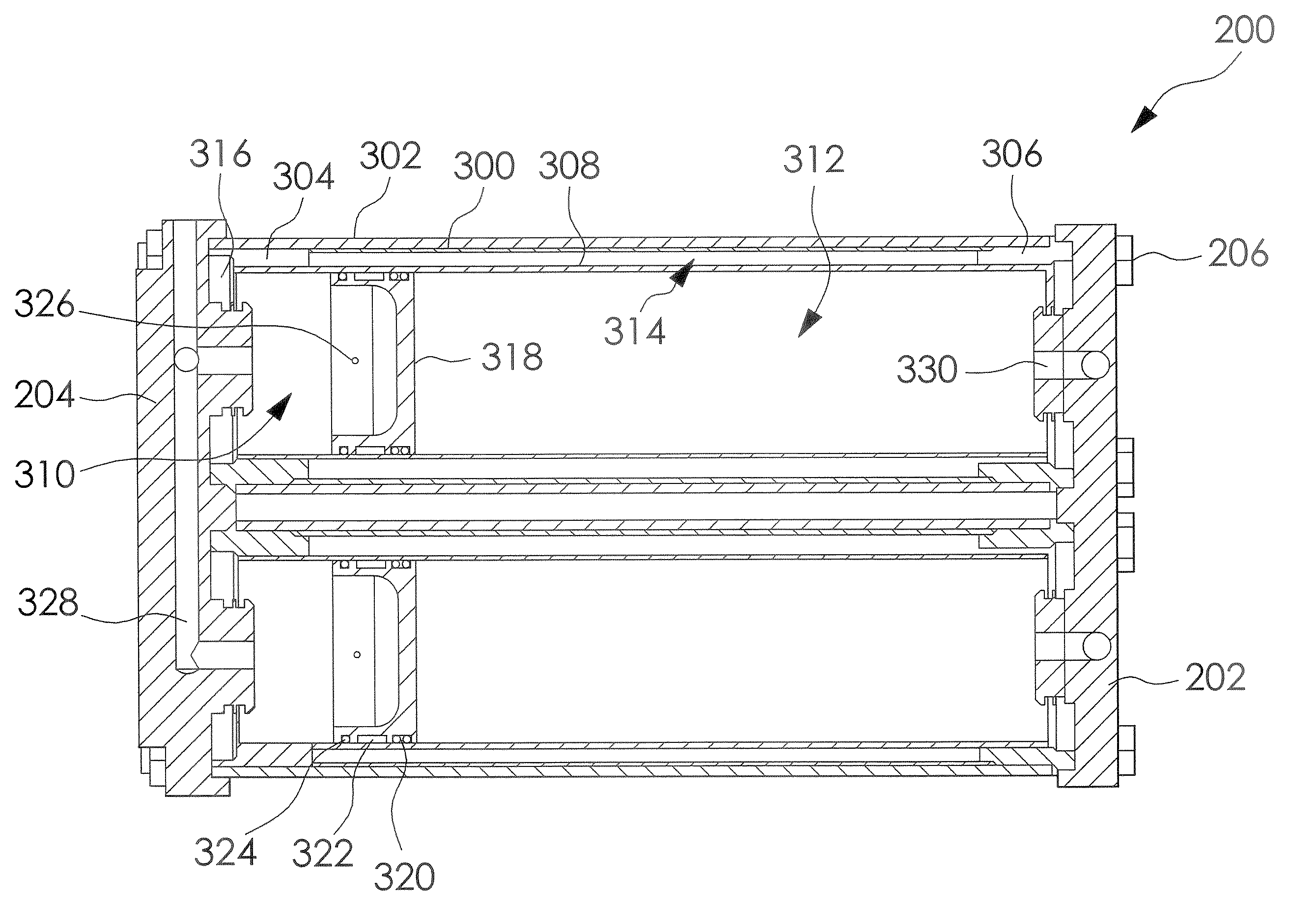
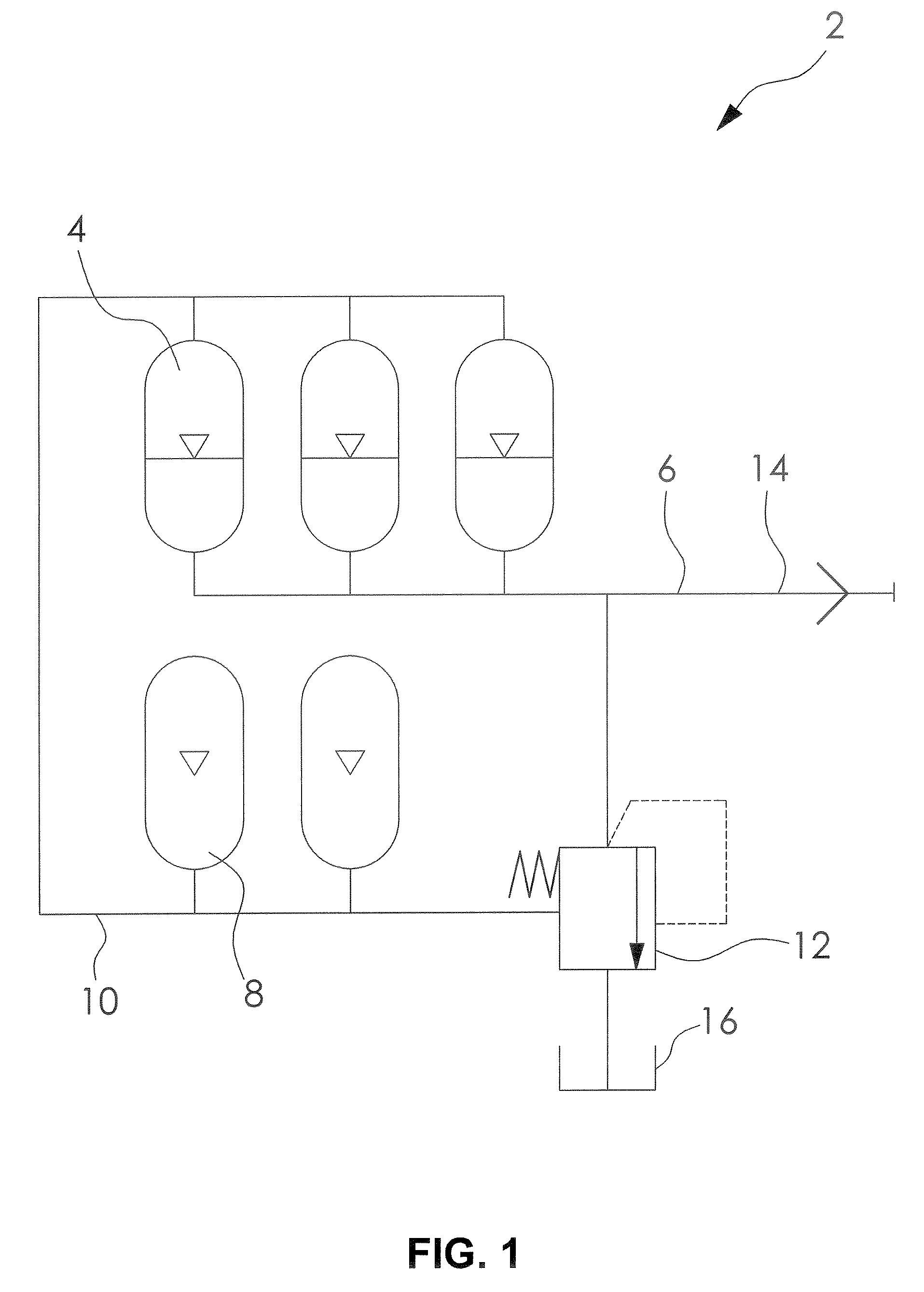
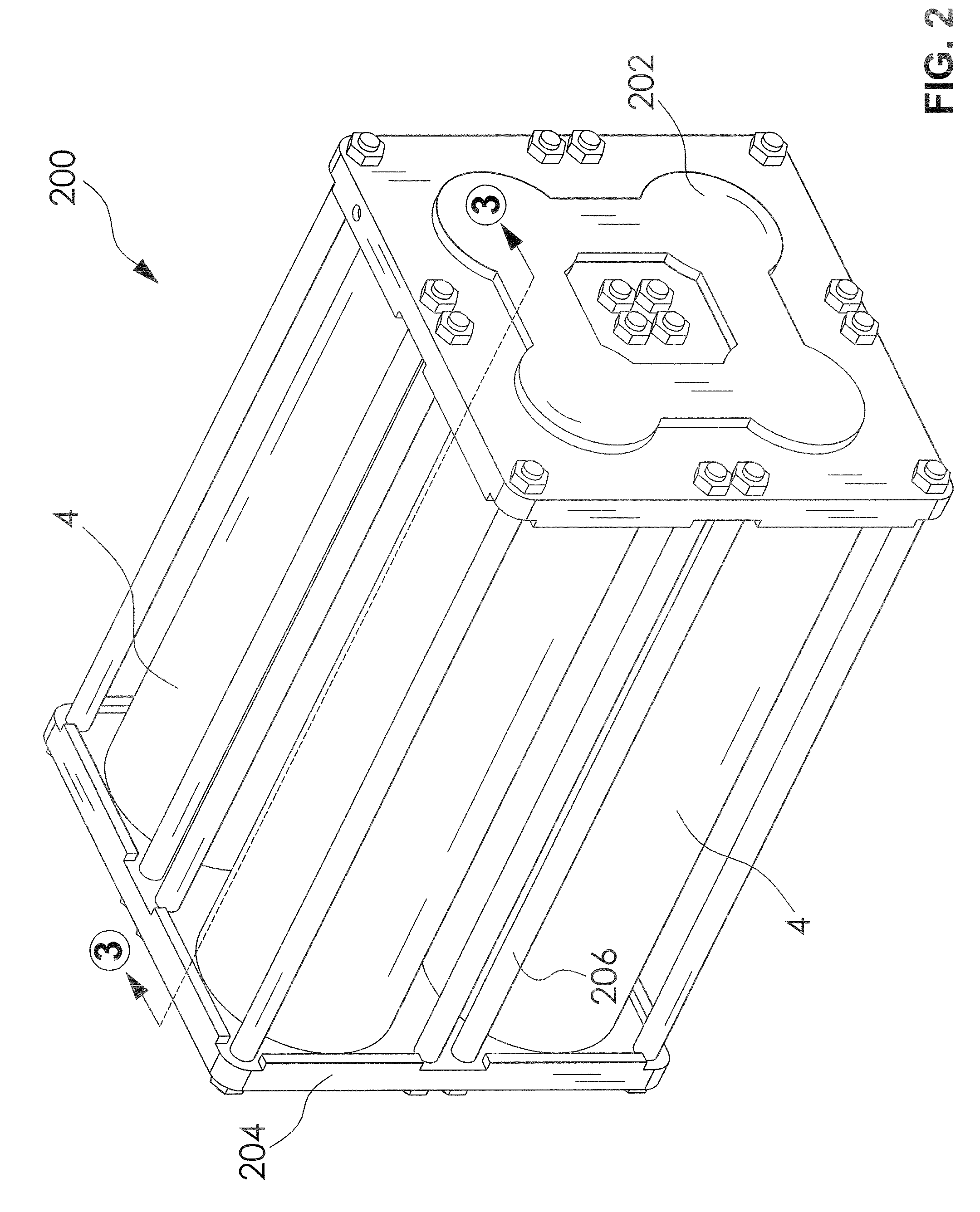
[0035]An overall schematic representation of an accumulator system 2 is shown in FIG. 1. The accumulator system 2 is comprised of at least one accumulator cylinder 4, whose fluid-side connections are joined to a common fluid network 6; zero or more auxiliary gas cylinders 8, whose gas-side connections share a common gas network 10 with the accumulator cylinders 4, and a gas-mediated, differential pressure relief valve 12. The accumulator system 2 is coupled to the primary hydraulic circuitry by connector 14, and the relief valve 12 has a connection to a reservoir tank 16.

[0036]...


PUM


Abstract

A lightweight, optimally efficient, easily serviced, piston-in-sleeve high pressure accumulator is provided. The accumulator includes one or more cylindrical composite pressure vessel separate end cap manifolds. A piston slidably disposed in a thin impermeable internal sleeve in the accumulator separates two chambers, one adapted for containing a working fluid and the other adapted for containing gas under pressure. Gas is provided in a volume between the impermeable internal sleeve and the composite pressure vessel wall. Additional gas is optionally provided in gas cylinders. Further components are provided for withstanding harmful effects of radial flexing of the composite vessel wall under high pressures, and from stresses present in use in mobile applications such as with a hydraulic power system for a hydraulic hybrid motor vehicle.

Description

CROSS-REFERENCE TO RELATED APPLICATIONS[0001]This application claims the benefit of U.S. Provisional Application No. 60 / 943,930, filed on Jun. 14, 2007. The entire disclosure of the above application is hereby incorporated herein by reference.FIELD OF THE INVENTION[0002]The present disclosure relates generally to accumulators for high pressure applications, and more particularly to high pressure accumulators of the piston-in-sleeve (or “piston and sleeve”) type. The disclosure further relates to the potential use of such accumulators in conjunction with fuel efficient hydraulic hybrid motor vehicles.BACKGROUND OF THE INVENTION[0003]1. Hydraulic Hybrid Vehicles[0004]Hybrid powertrains are an increasingly popular approach to improving the fuel utilization of motor vehicles. The term “hybrid” refers to the combination of a conventional internal combustion engine with an energy storage system, which typically serves the functions of receiving and storing excess energy produced by the en...

Claims


Application Information

Patent Timeline
IPC IPC(8): F15B1/24
CPCB60K6/12F15B1/24F15B2201/205F15B2201/31Y02T10/6208F15B2201/4056F15B2211/212F15B2211/50518F15B2201/32Y10T137/7837Y02T10/62
Inventor O'BRIEN, II, JAMES A.ROSTON, GERALDHUBBS, RALPH
Owner NRG ENTERPRISES
Why Eureka
Try Eureka