System and Process for Removal of Phosphorous and Ammonia from Aqueous Streams

Inactive Publication Date: 2008-12-18
JANSEN ROBERT +7
View PDF11 Cites 16 Cited by
  • Summary
  • Abstract
  • Description
  • Claims
  • Application Information

AI Technical Summary

Benefits of technology

[0006]In one embodiment, the present invention relates to a process for the removal of phosphorous and ammonia from an aqueous stream by contacting the aqueous stream with magnesium and base in a first zone having a first pH, to form an (n−1)th mixed stream and a first portion of struvite; separating the (n−1)th mixed stream from the first portion of struvite; removing at least some struvite from the first portion of struvite; contacting the (n−1)th mixed stream with base in an nth zone, wherein n is an integer incrementing from 2 to nmax, wherein nmax

Problems solved by technology

A problem often experienced with struvite in industrial systems (waste water treatment plants etc) is that it

Method used


Image

  • System and Process for Removal of Phosphorous and Ammonia from Aqueous Streams
  • System and Process for Removal of Phosphorous and Ammonia from Aqueous Streams
  • System and Process for Removal of Phosphorous and Ammonia from Aqueous Streams

Examples


example 1

Synthetic Waste Streams—4-Zone / 4-Vessel System

[0076]Background

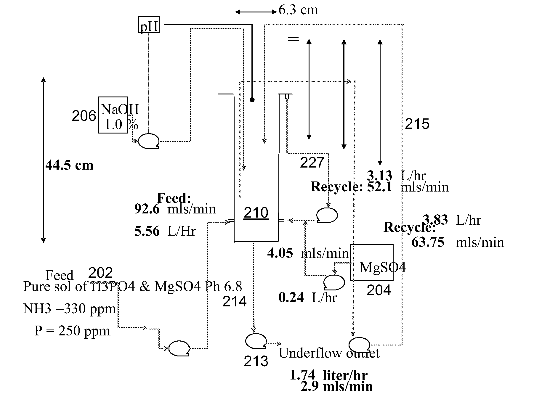
[0077]In this example, a synthetic feed stream containing 500 ppm of NH4+ and 433 ppm of phosphorous was dosed with 590 ppm of Mg (added in the form of MgSO4). The experimental set up is shown in FIG. 2.

[0078]Methodology

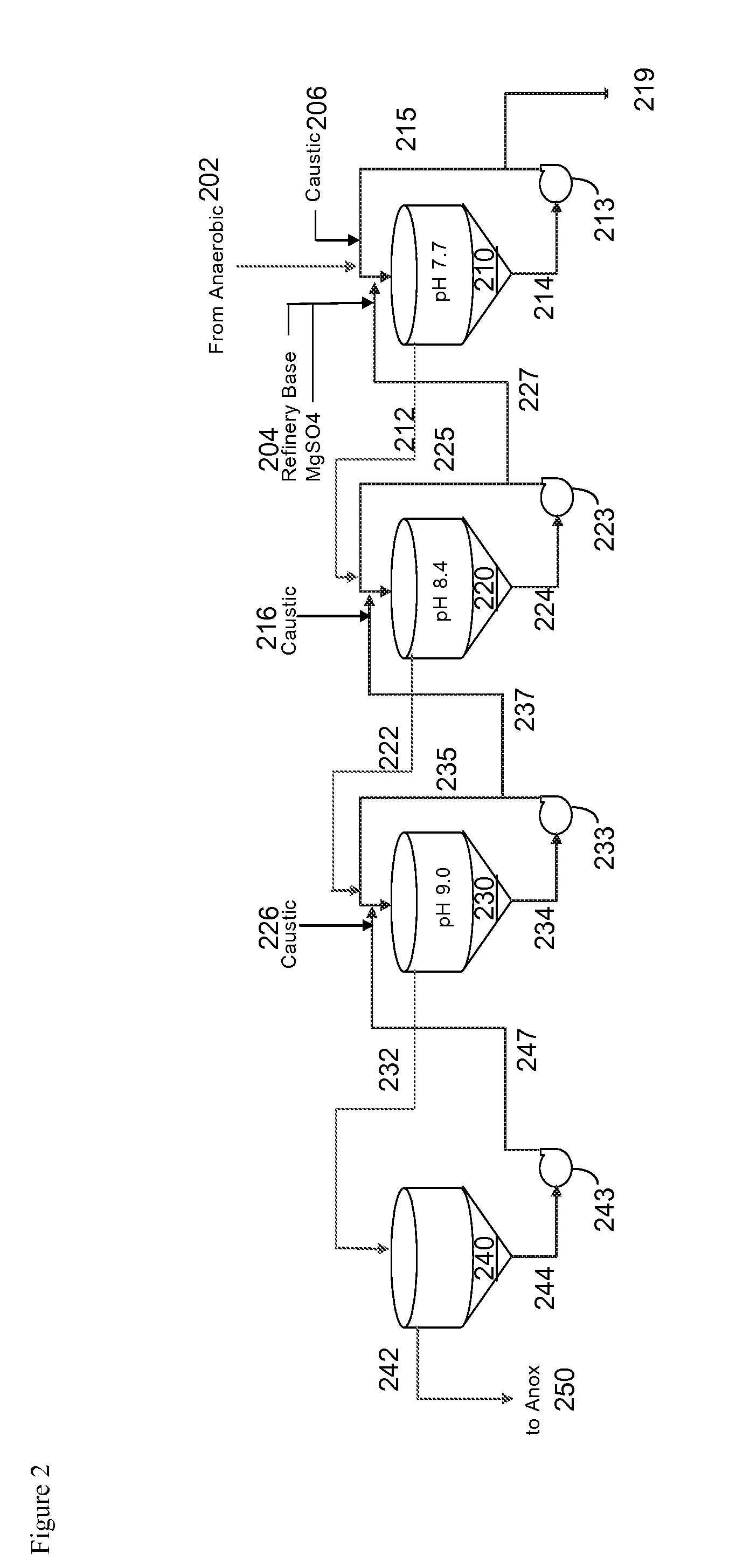
[0079]The synthetic feed stream was fed into reactor 210 at its base. Concomitantly, the MgSO4 solution 204 and caustic base 206 were dosed into the same reaction zone to achieve maximum mixing of these three streams (see FIG. 3). The flow of caustic was controlled to meet a target pH of 7.7. A recycle loop 214, 213, 215 within reactor 210 was used to establish equilibrium in the series of reactors—once the whole system had reached steady state, this recycle loop could be diverted to a screen to capture 219 the struvite crystals formed.

[0080]Overflow from reactor 210 was allowed to pass to the second reactor 220, where the same reactor design enabled efficient mixing of this stream with more caustic 216—th...

example 2

Waste Streams from a Corn Refinery Waste Water Treatment Process—1 Vessel System

[0087]Background

[0088]In this example, the conditions required to achieve optimal phosphorous removal were established in one reaction vessel. The dimensions of the vessel 510 and the streams into and out of the vessel are shown in FIG. 5.

[0089]Experimental

[0090]The incoming stream 502 contains a molar excess of ammonium and phosphorous. To achieve the supersaturation conditions required to make struvite, it was necessary to supplement the amount of Mg ions in the reactor. This was done by feeding a stream 504 of MgCl2 under controlled conditions such that the excess Mg exiting in the final stream was minimized.

[0091]The pH profile across the reactor was established using two streams. One of these streams was caustic ion exchange waste (a medium-high pH waste stream from the corn refinery). This stream was mixed with the MgCl2 and injected into the reactor at a height of 25%. The other high pH stream was...

example 3

Waste Streams from a Corn Refinery Waste Water Treatment Process—2 Vessel System

[0095]The apparatus, consisting of two reactors (S1 and S2), was set up as shown in FIG. 7. Physical parameters of S1 and S2: diameter 6 in, height 12 in, volume 1.47 gal. A typical run was characterized by (S1) Hydraulic Residence Time (HRT) 9.1 min and velocity 2.00 m / hr and (S2) HRT 8.7 min and velocity 2.11 m / hr. Overflow 2 led to an optional filter, not shown.

[0096]The feed to S1 was the product stream from an anaerobic digester (27 L / hr, 0.3 wt % solids, 417 ppm P, 263 ppm NH3). This feed was mixed with a dilute NaOH (0.4% soln, 8.4 L / hr) stream in a mixing section in S1, along with a solution of MgCl2 (1.1 L / hr). The pH in S1 was 7.8-8. The underflow from S1 (spin test solids content=15%) was circulated at a rate of 33 L / hr, with 0.5 L / hr of struvite particles being drawn off. The struvite crystals are separated from the recycle stream by passing the whole through a screen.

[0097]The overflow strea...


PUM

PropertyMeasurementUnit
Speedaaaaaaaaaa
Speedaaaaaaaaaa
Speedaaaaaaaaaa

Abstract

We disclose a process for the removal of phosphorous and ammonia from an aqueous stream by contacting the aqueous stream with magnesium and base in a first zone having a first pH, to form an (n−1)th mixed stream and a first portion of struvite; separating the (n−1)th mixed stream from the first portion of struvite; removing at least some struvite from the first portion of struvite; contacting the (n−1)th mixed stream with base in an nth zone, wherein n is an integer incrementing from 2 to nmax, wherein nmax is an integer from 2 to about 5, and wherein the nth zone has an nth pH higher than the (n−1)th pH, to form an nth mixed stream and an nth portion of struvite, except no base is added and the nth pH need not be higher than the (n−1)th pH when n=nmax; separating the nth mixed stream from the nth portion of struvite; returning the nth portion of struvite to the (n−1)th zone; and, if n<nmax, incrementing n and repeating the second contacting, second separating, and returning steps, or, if n=nmax, releasing the nth mixed stream to a treated water tank. We also disclose a system which can be used for performing the method.

Description

[0001]This application claims priority from U.S. provisional patent application Ser. No. 60 / 895,165, filed on Mar. 16, 2007, which is incorporated herein by reference.BACKGROUND OF THE INVENTION[0002]The present invention relates generally to the field of waste water treatment. More particularly, it concerns the removal of phosphorous and ammonia from aqueous streams.[0003]Phosphorous compounds and ammonia are generated in a number of biological and industrial processes, such as refining of grains such as corn. Phosphorous compounds and ammonia have relatively low value and, in the past, have frequently been disposed of by discharge of the untreated compounds into bodies of water. However, when present in bodies of water at elevated concentrations, phosphorous and ammonia may promote algae blooms, leading to localized hypoxia of the body of water and dying off of fish. The desire to avoid algae blooms and fish kills has led to reductions in the amount of allowable discharge of phosp...

Claims


Application Information

Patent Timeline
IPC IPC(8): B01J20/04
CPCB01D9/004C02F1/5254C02F2101/105C02F2101/16C02F2103/06C02F2103/32B01D9/005
Inventor JANSEN, ROBERTCAMBORIEUX, SEBASTIENKENNY, GENEVIEVETANNER, RICHARDLUPPES, LORENBAIADA, ANTHONYKERR, JOHNWINDEBANK, TIMOTHY
Owner JANSEN ROBERT
Why Eureka
Try Eureka