
Systems and methods for power generation with exhaust gas recirculation

Active Publication Date: 2008-12-18
GENERAL ELECTRIC CO
View PDF13 Cites 254 Cited by
  • Summary
  • Abstract
  • Description
  • Claims
  • Application Information

AI Technical Summary

Benefits of technology

[0007]In yet another aspect, a method of generating power includes compressing a feed oxidant and generating a compressed oxidant in a compressor, combusting a fuel stream and the compressed oxidant in a combustion chamber and generating a discharge and expanding the discharge from the combustion chamber and generating an exhaust comprising carbon dioxide and electrical energy. The method further includes splitting the exhaust into a first split stream and a second split stream using a coanda ejector, recovering heat from the first split stream and generating a cooled first split stream, increasing the pressure of the cooled first split stream and remixing the cooled first split stream and the second split stream and generating a mixed exhaust. The method also includes purifying the mixed exhaust and generating a recycle stream mixing the recycle stream with fresh oxidant and generating the feed oxidant; and releasing a portion of the cooled first exhaust through a first control valve and releasing a portion of the recycle stream through a second control valve.

Problems solved by technology

Removal or recovery of the carbon dioxide (CO2) from power generation systems, such as from the exhaust of a gas turbine, is generally not economical due to low CO2 content and low (ambient) pressure of the exhaust.
Therefore, unfortunately, the exhaust containing the CO2 is typically released to the atmosphere, and does not get sequestered into oceans, mines, oil wells, geological saline reservoirs, and so on.

Method used


Image

  • Systems and methods for power generation with exhaust gas recirculation
  • Systems and methods for power generation with exhaust gas recirculation
  • Systems and methods for power generation with exhaust gas recirculation

Examples


Embodiment Construction

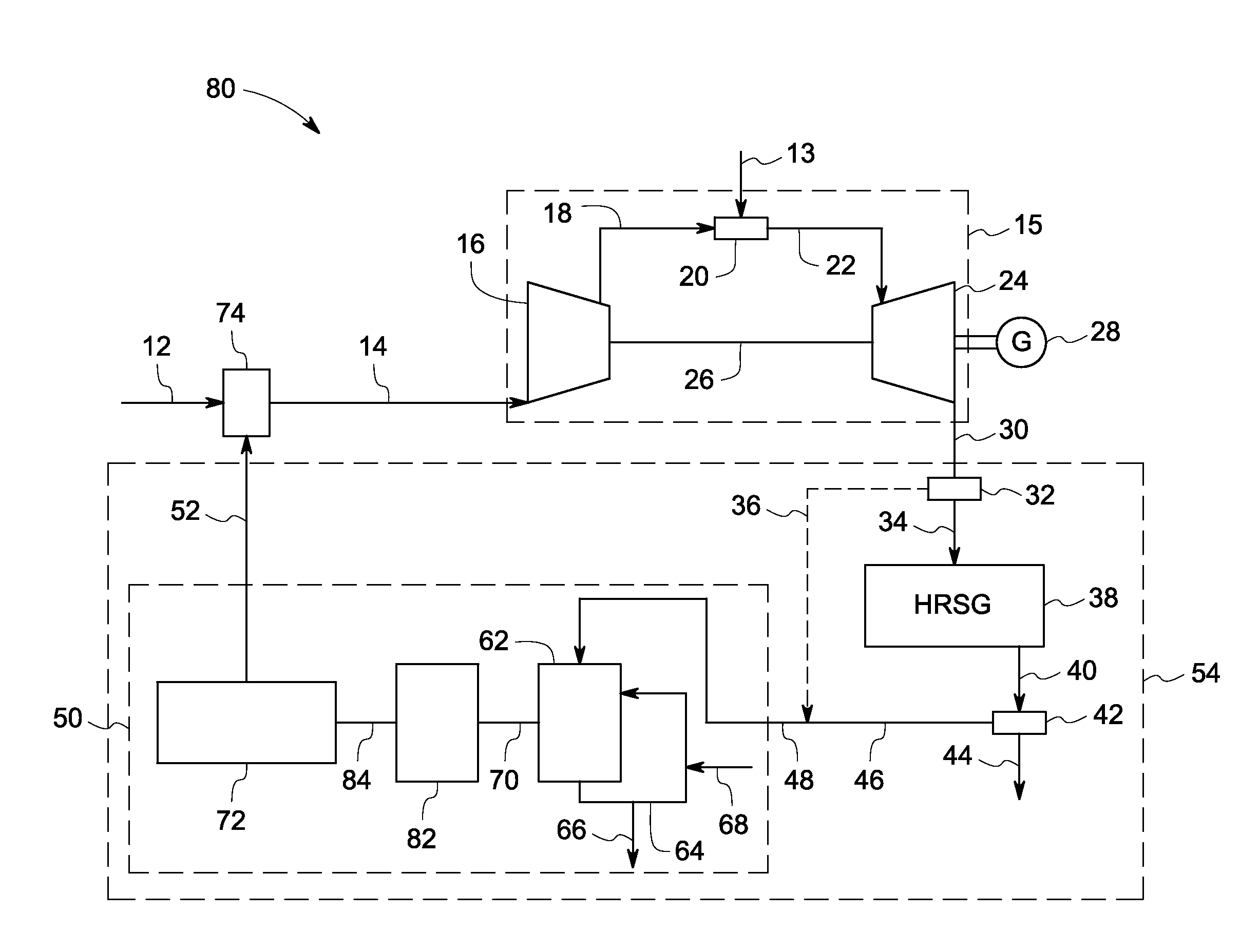
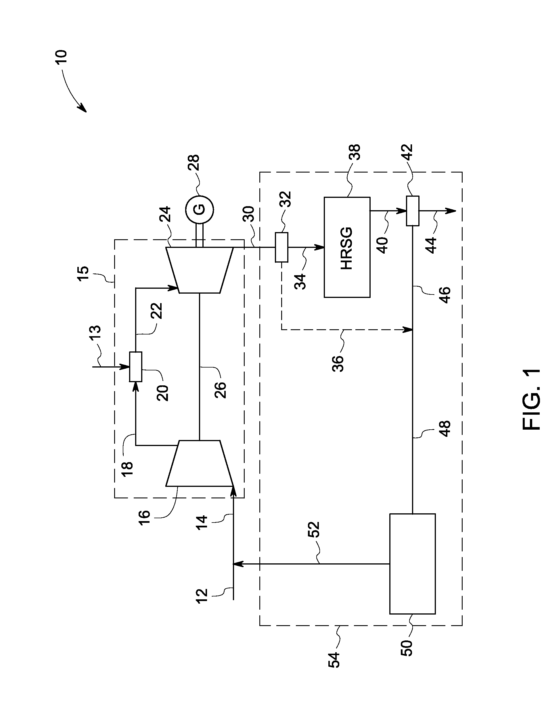
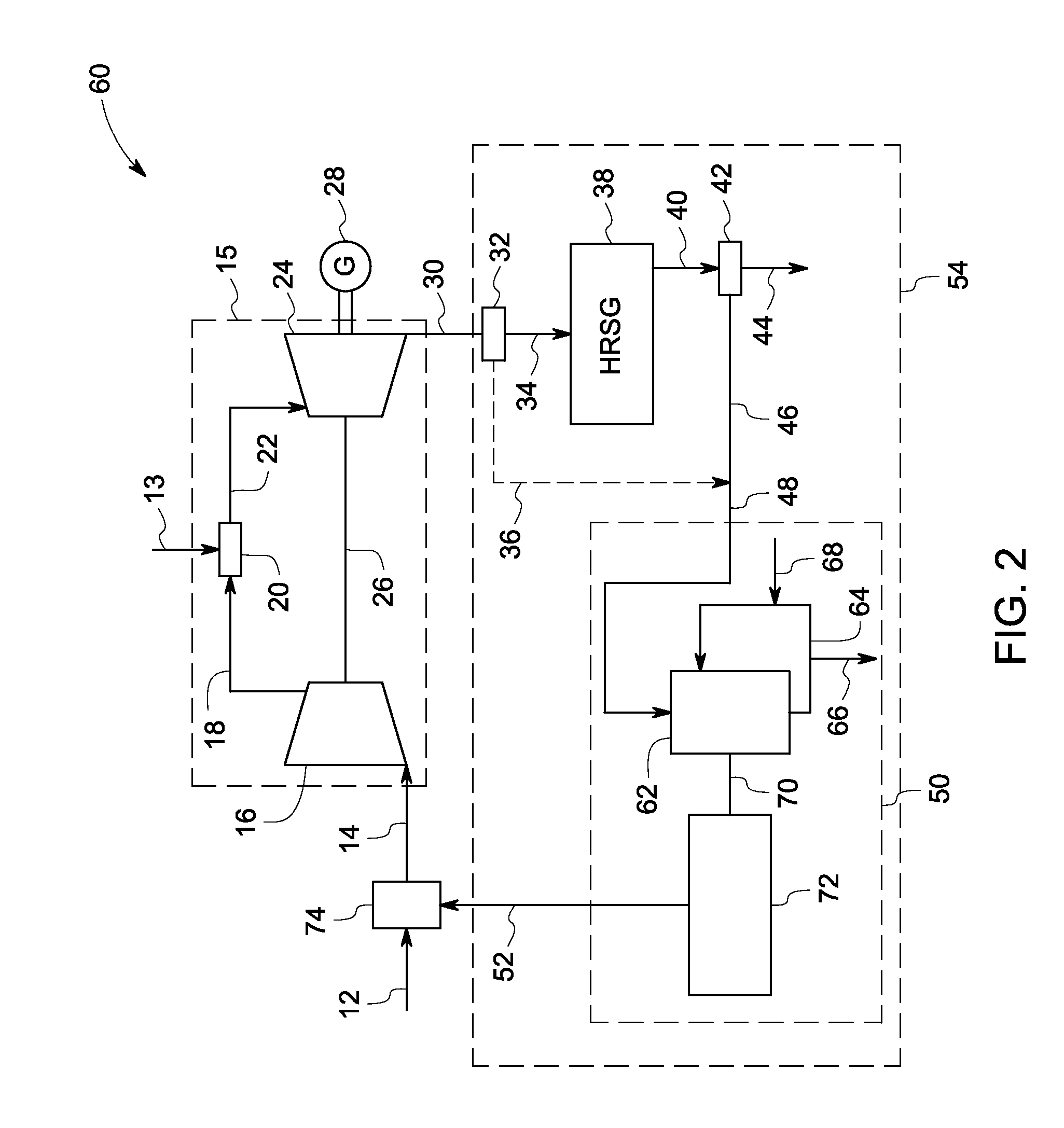
[0017]The present technique provides for one or more exemplary gas turbine systems operating in a power generation system to generate power with low NOx and CO2 emissions. A portion of the exhaust from the gas turbine is re-circulated into the inlet of the turbine, which portion of the exhaust is blended with fresh oxidant such as air before being introduced to the combustion chamber of the turbine system. As a result the blended oxidant used for combustion has lower oxygen content when compared to a conventional oxidant and results in low NOx emission in the discharge from the combustion chamber. Additionally the carbon dioxide generated in the combustion process is concentrated as a portion of the exhaust gas is re-circulated back to the turbine system which re-circulation enhances the CO2 separation processes downstream. The present techniques also provide a purification process to purify the exhaust gas before being re-circulated back into the turbine system. This purification p...


PUM


Abstract

A power generation system includes a gas turbine system. The turbine system includes a combustion chamber configured to combust a fuel stream a compressor configured to receive a feed oxidant stream and supply a compressed oxidant to the combustion chamber and an expander configured to receive a discharge from the combustion chamber and generate an exhaust comprising carbon dioxide and electrical energy. The system further includes a retrofittable exhaust gas recirculation system including a splitter configured to split the exhaust into a first split stream and a second split stream, a heat recovery steam generator configured to receive the first split stream and generate a cooled first split stream and a purification system configured to receive the first cooled split stream and the second split stream and generate a recycle stream, wherein the recycle stream is mixed with the fresh oxidant to generate the feed oxidant stream.

Description

[0001]This application claims priority to and the benefit of provisional U.S. Patent Application No. 60 / 943,734, entitled “LOW NOX HIGH CO2 COMBUSTOR, GAS TURBINE AND CYCLE FOR LOW EMISSIONS POWER GENERATION”, filed on Jun. 13, 2007, which is hereby incorporated by reference in its entirety.BACKGROUND[0002]The invention relates generally to power generation and the efficient recovery of carbon dioxide. More particularly, the invention relates to the integration of gas-turbine exhaust recirculation with reduced NOx emission.[0003]Power generation systems that combust fuels containing carbon (e.g., fossil fuels) produce carbon dioxide (CO2) as a byproduct, because in the combustion, carbon is converted to CO2. Typically air is used as an oxidant for the fuel combustion forming NOx. Removal or recovery of the carbon dioxide (CO2) from power generation systems, such as from the exhaust of a gas turbine, is generally not economical due to low CO2 content and low (ambient) pressure of the...

Claims


Application Information

Patent Timeline
IPC IPC(8): F02C6/00F02C3/34F02G5/02
CPCF02C3/34Y02E20/16F02C7/10F02C7/08
Inventor EVULET, ANDREI TRISTANELKADY, AHMED MOSTAFABOWMAN, MICHAEL JOHN
Owner GENERAL ELECTRIC CO
Learn More