Method and apparatus for removal of vaporized hydrogen peroxide from a region

a technology method, which is applied in the direction of life-saving devices, chemical/physical/physicochemical processes, and diseases, can solve the problems of less efficient decomposition of vaporized hydrogen peroxide into water vapor and molecular oxygen, reducing the residence time of contact between the elements of the catalytic destroyer, and vaporizing hydrogen

Active Publication Date: 2008-12-18
AMERICAN STERILIZER CO
View PDF52 Cites 11 Cited by
  • Summary
  • Abstract
  • Description
  • Claims
  • Application Information

AI Technical Summary

Benefits of technology

[0010]An advantage of the present invention is the provision of a method and apparatus for aeration wherein concentrations of a gaseous / vaporous sterilant is reduced within a region.
[0011]Another advantage of the present invention is the provision of a method and apparatus for aeration that uses reactive chemistry to remove a gaseous / vaporous sterilant from a region.
[0012]Still another advantage of the present invention is the provision of a method and apparatus for aeration wherein both large and small concentrations of a gaseous / vaporous sterilant are reduced within a region.
[0013]These and other advantages will become apparent from the following description taken together with the accompanying drawings and the appended claims.

Problems solved by technology

However, at low concentrations of vaporized hydrogen peroxide such catalytic destroyers are less efficient at decomposing vaporized hydrogen peroxide into water vapor and molecular oxygen.
This may be especially problematic when the air carrying the vaporized hydrogen peroxide is forced through the catalytic destroyer at a high rate, thus reducing the residence time of contact between the elements of the catalytic destroyer (e.g., copper) and the vaporized hydrogen peroxide.

Method used


Image

  • Method and apparatus for removal of vaporized hydrogen peroxide from a region
  • Method and apparatus for removal of vaporized hydrogen peroxide from a region
  • Method and apparatus for removal of vaporized hydrogen peroxide from a region

Examples


first embodiment

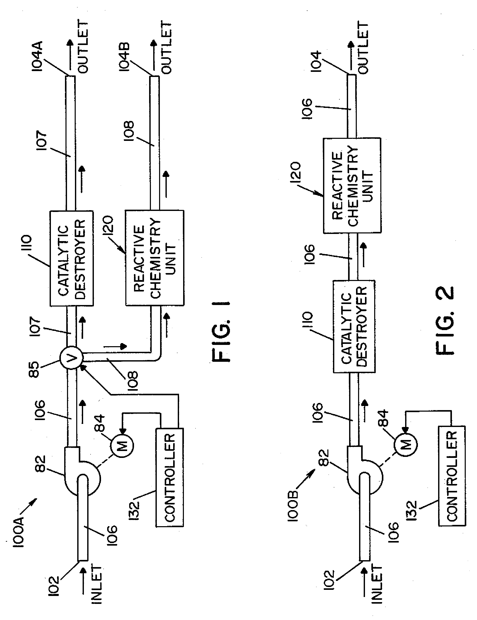
[0019]Referring now to the drawings wherein the showings are for the purpose of illustrating embodiments of the invention only, and not for the purpose of limiting same, FIG. 1 shows an aeration system 100A according to the present invention. Aeration system 100A includes a first conduit 106, a second conduit 107 and a third conduit 108.

[0020]A valve 85 is a three-position valve moveable between a first position wherein first conduit 106 is in fluid communication only with second conduit 107, a second position wherein first conduit 106 is in fluid communication only with third conduit 108, and a third position wherein first conduit 106 is in fluid communication with both second conduit 107 and third conduit 108.

[0021]An inlet 102 is located at one end of first conduit 106. Inlet 102 is in fluid communication with a region (not shown). A first outlet 104A is located at one end of second conduit 107 and a second outlet 104B is located at one end of third conduit 108. First and second ...

second embodiment

[0031]FIG. 2 shows an aeration system 1001B according to the present invention. Aeration system 1GOB includes a first conduit 106 having an inlet 102 at a first end and an outlet 104 at a second end. Inlet 102 is in fluid communication with a region (not shown). Outlet 104 may be in fluid communication with the region, thereby forming a closed loop system comprised of the region and aeration system 100B.

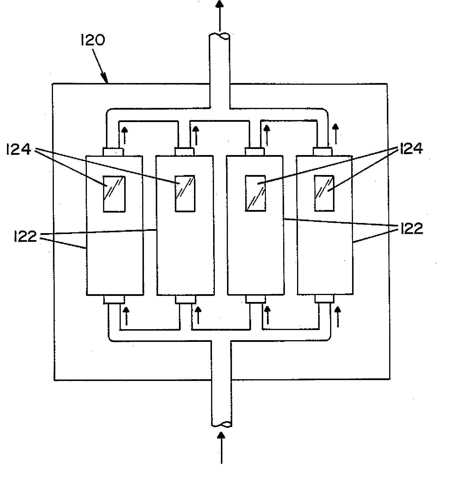
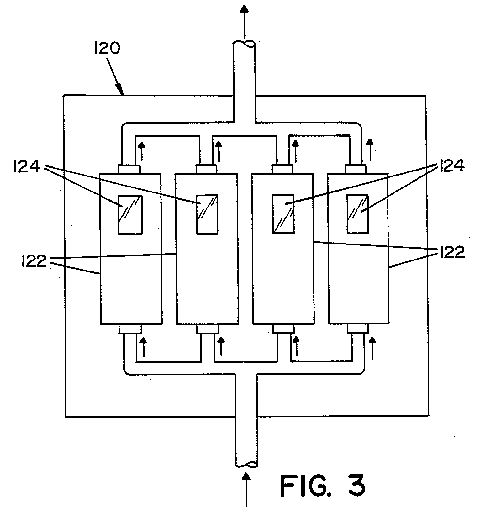
[0032]A blower 82, driven by a motor 84, is disposed within conduit 106. A catalytic destroyer 110 and a reactive chemistry unit 120 are disposed within conduit 106 in series. Catalytic destroyer 110 and reactive chemistry unit 120 are described in detail above in connection with the embodiment of FIG. 1. A controller 132 controls operation of aeration system 110B, including motor 84.

[0033]It is contemplated that the aeration system of the present invention may be integrated into a vaporized hydrogen peroxide (vhp) sterilization system used to sterilize an enclosure (e.g., room, labo...


PUM

PropertyMeasurementUnit
concentrationaaaaaaaaaa
color changeaaaaaaaaaa
chemical changeaaaaaaaaaa

Abstract

A method and apparatus for aerating a region exposed to a gaseous/vaporous sterilant. A catalytic destroyer and a reactive chemical unit are used to reduce the concentration of the gaseous/vaporous sterilant within the region. The reactive chemical unit includes a chemistry that is chemically reactive with the gaseous/vaporous sterilant. In one embodiment, the gaseous/vaporous sterilant is vaporized hydrogen peroxide and the chemistry of the reactive chemical unit includes thiosulfate and iodide.

Description

FIELD OF THE INVENTION[0001]The present invention relates generally to the art of sterilization using a gaseous or vaporous chemical agent, and more particularly to a method and apparatus for reducing both large and small concentrations of vaporized hydrogen peroxide in a region by use of a reactive chemistry, such as a reducing agent.BACKGROUND OF THE INVENTION[0002]An enclosure defining a region (e.g., hotel rooms, offices, laboratories, buildings, cruise ships, airport terminals, and the like) may be sterilized by exposing the region (and any articles therein) to a sterilizing agent, such as vaporized hydrogen peroxide. Vaporized hydrogen peroxide may be generated by vaporizing a metered quantity of an aqueous solution of hydrogen peroxide (e.g., about 30% to 59% hydrogen peroxide, by weight). The vaporized hydrogen peroxide is carried into the region by a carrier gas (e.g., air). As used herein the term “sterilization” includes, but is not limited to, sterilization, disinfection...

Claims


Application Information

Patent Timeline
Patent Type & Authority Applications(United States)
IPC IPC(8): A61L9/015B01J19/00
CPCA61L2/202A61L2/206A61L2/208A61L9/015A61L2202/13
Inventor CENTANNI, MICHAEL A.BURKE, PETER A.
Owner AMERICAN STERILIZER CO
Why Eureka
Try Eureka