Method for fuel cell start-up with uniform hydrogen flow

a fuel cell and flow-based technology, applied in the direction of fuel cells, fuel cell groupings, electrical devices, etc., can solve the problems of severe performance degradation of the fuel cell stack, cell voltage degradation induced by carbon corrosion, non-uniform hydrogen distribution, etc., to achieve the effect of reducing hydrogen exhaust emissions

Active Publication Date: 2008-12-18
GM GLOBAL TECH OPERATIONS LLC
View PDF11 Cites 29 Cited by
  • Summary
  • Abstract
  • Description
  • Claims
  • Application Information

AI Technical Summary

Benefits of technology

[0011]In concordance with the instant disclosure, a fuel cell system and method that optimizes a distribution of hydrogen, militates against voltage degradation, and minimizes hydrogen exhaust emissions during a fuel cell stack start-up operation is surprisingly discovered.

Problems solved by technology

In all these cases there is a non-uniform distribution of hydrogen.
It is also well known in the art that high cell voltage combined with a hydrogen-air front passing through the cell results in cell voltage degradation induced by carbon corrosion.
Unfortunately, non-uniform distribution of hydrogen to the fuel cells during the start-up operation and the use of a resistive load can lead to a severe performance degradation of fuel cell stack.
The presence of air on the cathodes coupled with the hydrogen-air front on the anodes can cause an undesirable electric potential to form.
In particular, the non-uniform distribution of hydrogen on the anodes of the fuel cell stack can lead to a high potential phenomenon known as “cell reversal.” Cell reversal occurs when a load is applied to the fuel cell stack and when at least one fuel cell in the fuel cell stack lacks hydrogen while other fuel cells in the fuel cell stack are supplied with hydrogen.
Cell reversal causes an oxidation of fuel cell components and may result in a rapid voltage degradation of the fuel cell stack.
In particular, a corrosion of the carbon substrate of the electrodes, wherein surface oxides, CO, and CO2 are formed, occurs.
The voltage degradation significantly reduces the useful life of the fuel cell stack.
Such a method has been found to result in the non-uniform distribution of hydrogen at the fuel cells disposed at the center of the fuel cell stack, however.

Method used


Image

  • Method for fuel cell start-up with uniform hydrogen flow
  • Method for fuel cell start-up with uniform hydrogen flow
  • Method for fuel cell start-up with uniform hydrogen flow

Examples


Embodiment Construction

[0023]The following description is merely exemplary in nature and is not intended to limit the present disclosure, application, or uses. It should also be understood that throughout the drawings, corresponding reference numerals indicate like or corresponding parts and features. In respect of the methods disclosed, the steps presented are exemplary in nature, and thus, are not necessary or critical.

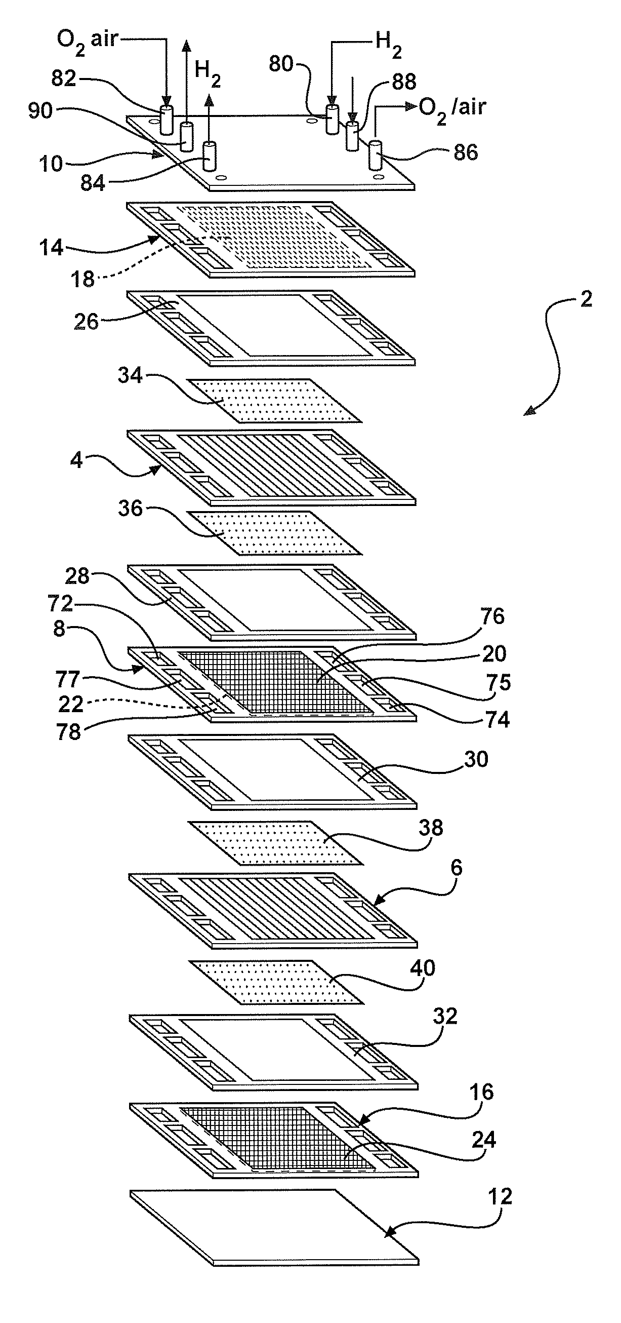
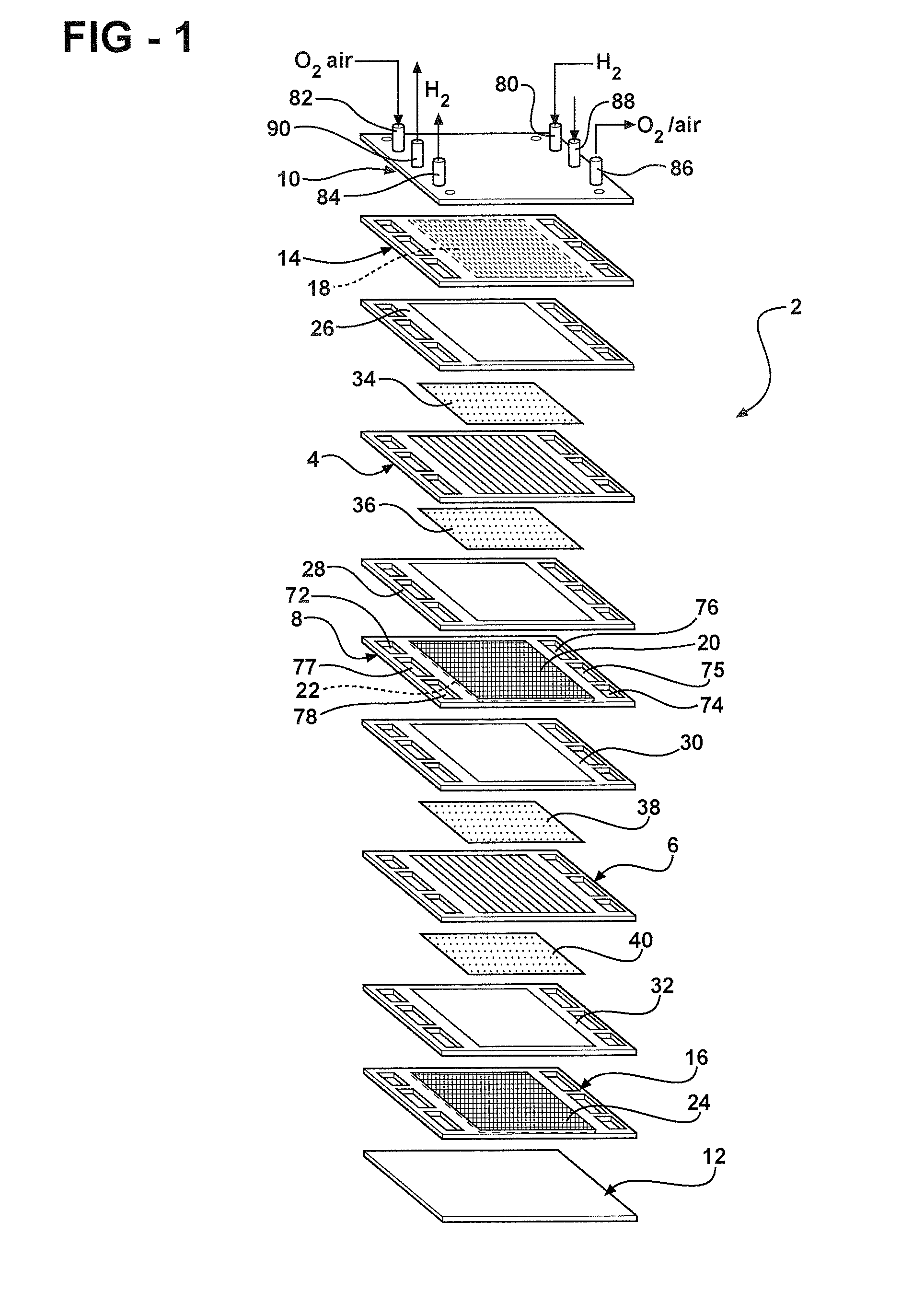
[0024]For simplicity, only a two-cell stack (i.e. one bipolar plate) is illustrated and described in FIG. 1, it being understood that a typical fuel cell stack will have many more such cells and bipolar plates.

[0025]FIG. 1 depicts an illustrative two-cell, bipolar PEM fuel cell stack 2 having a pair of MEAs 4, 6 separated from each other by an electrically conductive bipolar plate 8. The MEAs 4, 6 and bipolar plate 8 are stacked together between a pair of clamping plates 10, 12, and a pair of unipolar end plates 14, 16. The clamping plates 10, 12 are electrically insulated from the end pl...


PUM

PropertyMeasurementUnit
voltageaaaaaaaaaa
voltageaaaaaaaaaa
voltageaaaaaaaaaa

Abstract

A fuel cell system is provided having a fuel cell stack including a plurality of fuel cells. The fuel cell system includes an anode supply manifold in fluid communication with the plurality of fuel cells, the anode supply manifold adapted to deliver a anode supply stream to the plurality of fuel cells; an anode exhaust manifold in fluid communication with the anodes of the plurality of fuel cells, the anode exhaust manifold adapted to receive an anode exhaust stream from the plurality of fuel cells; a first valve in fluid communication with the anode supply manifold; and a second valve in fluid communication with the anode exhaust manifold. A method of starting the fuel cell system is also provided. The fuel cell system and method militates against a non-uniform distribution of the anode supply stream to the anodes of the plurality of fuel cells.

Description

FIELD OF THE INVENTION[0001]The present disclosure relates to a fuel cell system with substantially uniform hydrogen flow at start-up and a start-up method for the fuel cell system.BACKGROUND OF THE INVENTION[0002]Fuel cells have been proposed as a clean, efficient and environmentally responsible power source for electric vehicles and various other applications. In particular, fuel cells have been identified as a potential alternative for the traditional internal-combustion engine used in modern automobiles.[0003]A fuel cell typically includes three basic components: a cathode, an anode and an electrolyte membrane. The cathode and anode typically include a finely divided catalyst, generally platinum, supported on carbon particles and mixed with an ionomer. The electrolyte membrane is sandwiched between the cathode and the anode to form a membrane-electrolyte-assembly (MEA). The MEA is typically disposed between porous diffusion media (DM) which facilitate a delivery of gaseous react...

Claims


Application Information

Patent Timeline
Patent Type & Authority Applications(United States)
IPC IPC(8): H01M8/04H01M8/24
CPCH01M8/04223H01M8/04544H01M8/04753H01M8/04761H01M8/2465H01M8/249H01M2008/1095Y02E60/50H01M8/2483H01M8/04302H01M8/04225
Inventor SIENKOWSKI, JON R.LAKSHMANAN, BALASUBRAMANIANDARGA, DANIEL J.SALVADOR, JOHN P.
Owner GM GLOBAL TECH OPERATIONS LLC
Why Eureka
Try Eureka