Optimized cooling tube geometry for intimate thermal contact with cells

Inactive Publication Date: 2008-12-18
TESLA INC
View PDF8 Cites 115 Cited by
  • Summary
  • Abstract
  • Description
  • Claims
  • Application Information

AI Technical Summary

Benefits of technology

[0018]One advantage of the present invention may be that it provides a novel and improved thermal management system for a battery pack.
[0019]Still a further advantage of the present invention may be that it provides an optimized geometry cooling tube for use in an electrical vehicle.
[0020]Yet another advantage of the present invention may be that it provides a scalloped cooling tube for use in a thermal management system in an electric vehicle.
[0021]Yet another advantage of the present invention may be that it provides a scalloped cooling tube that will allow for more energy to be carried for a given batt

Problems solved by technology

Furthermore, many of these prior art electric vehicles need to be physically large and heavy to accommodate all of these batteries, such that these cars are not capable of achieving necessary acceleration, handling, performance and an extended range needed for an electric car to become a feasible option for public purchase and use.
Many prior art electrical vehicles are of normal size and not overly heavy in a very small range, thus reducing feasibility for large mass selling of such vehicles to the consuming public.
Furthermore, many of these prior art electric vehicles have problems with protecting the occupants in the vehicle from the high voltage components and high temperatures that emanate from such high voltage components and still provide a vehicle at acceptable speeds comparable to that of a gasoline or diesel internal combustion engine.
Many of these prior art electrical vehicles have had problems with the prior art batteries overheating, thus reducing the range of the electric vehicle and the durability and overall life of the batteries or cells that are part of the

Method used


Image

  • Optimized cooling tube geometry for intimate thermal contact with cells
  • Optimized cooling tube geometry for intimate thermal contact with cells
  • Optimized cooling tube geometry for intimate thermal contact with cells

Examples


Embodiment Construction

)

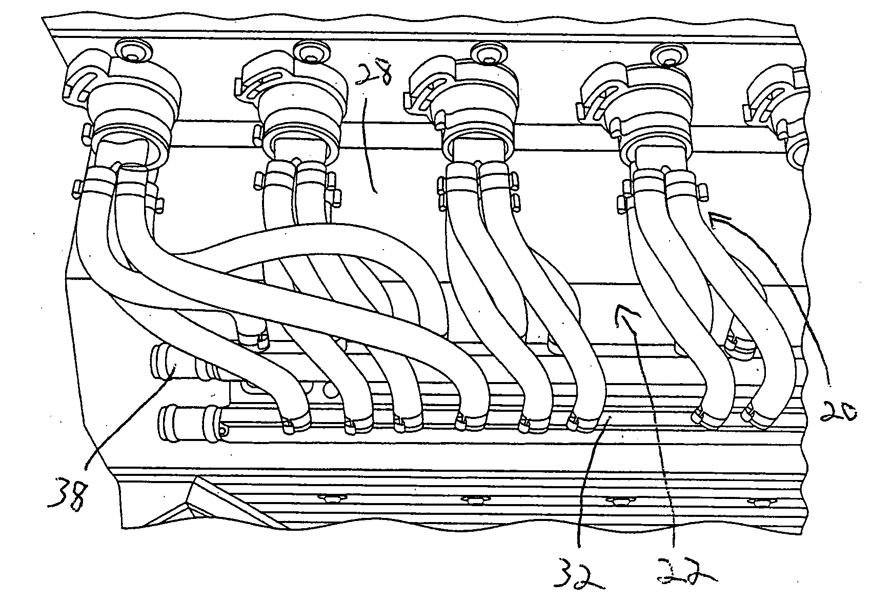
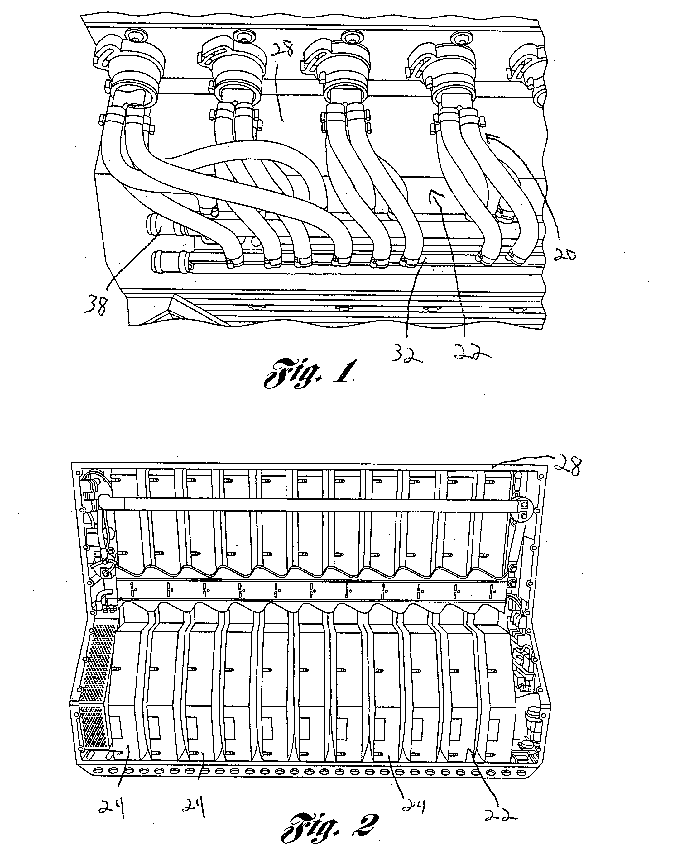
[0038]Referring to the drawings, a battery pack thermal management system 20 used with an energy storage system (ESS) 22 is shown. The energy storage system or battery pack 22 is generally comprised of a predetermined number of battery modules or sheets 24, a main control logic PSB, and a twelve volt power supply. In one contemplated embodiment the energy storage system 22 has eleven battery modules or sheets 24 which are capable of producing approximately 375 volts DC. This nominal voltage may operate an electric vehicle that will be capable of traveling many miles without recharging and is capable of delivering enough power and acceleration to compare favorably with internal combustion engines. In one contemplated embodiment, the ESS 22 may be capable of storing enough energy that the electric vehicle can travel approximately 200 miles without recharging. However, it should be noted that it is also contemplated to have an electric vehicle based on the present invention that can t...


PUM


Abstract

A battery pack thermal management system for use in an electrical vehicle is disclosed. The battery pack thermal management system includes a manifold and a plurality of cells arranged in a predetermined pattern within the battery pack. The system also includes a cooling tube having a scallop like outer surface in thermal contact with the cells and in fluid communication with the manifold. The thermal management system will cool the battery pack to a predetermined temperature to increase the longevity of the battery pack within the electric vehicle.

Description

BACKGROUND OF THE INVENTION[0001]1. Field of the Invention[0002]The subject invention generally relates to a thermal management system and more particularly relates to optimized cooling tube for use in a thermal management system in an electric vehicle.[0003]2. Description of Related Art[0004]It is well known in the prior art to use all electric automobiles to provide transportation for occupants. Many of these prior art electric automobiles carry several thousand pounds of nickel metal hydride batteries to achieve a long range electric vehicle for every day use by consumers. Furthermore, many of these prior art electric vehicles need to be physically large and heavy to accommodate all of these batteries, such that these cars are not capable of achieving necessary acceleration, handling, performance and an extended range needed for an electric car to become a feasible option for public purchase and use. Many prior art electrical vehicles are of normal size and not overly heavy in a ...

Claims


Application Information

Patent Timeline
IPC IPC(8): H01M10/50H01M50/213H01M50/291
CPCH01M2/1077Y02T10/7011H01M10/5016H01M10/503H01M10/5059H01M10/5077H01M10/5095B60L3/0046B60L11/1805B60L11/1874B60L11/1875B60L11/1879B60L2240/545Y02T10/7005Y02T10/705Y02T90/16H01M10/5004H01M10/625H01M10/663H01M10/6568H01M10/6557H01M10/643H01M10/613B60L50/52B60L58/26B60L58/27B60L50/64B60L58/21Y02T10/70Y02E60/10H01M50/213H01M50/291
Inventor HERMANN, WESTON ARTHURKOHN, SCOTTBERDICHEVSKY, GENE
Owner TESLA INC
Why Eureka
Try Eureka