[0009]An object of the present invention is to provide a selective reduction catalyst which can eliminate a need of mounting of an independent ammonia oxidation catalyst to an exhaust passage; and an engine exhaust gas purifier using it.
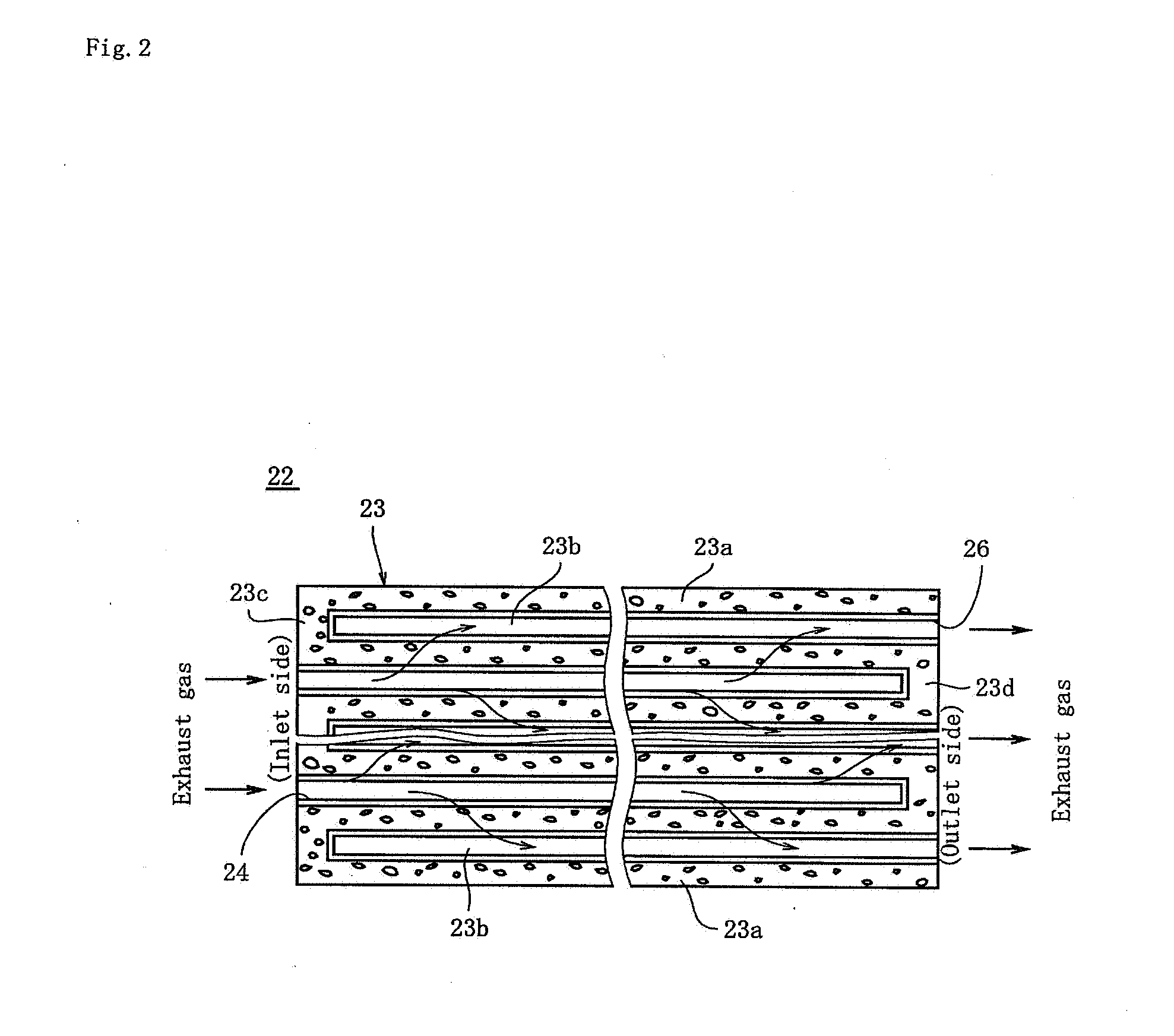
[0012]In the selective reduction catalyst described in claim 1, when the exhaust gas flows into the selective reduction catalyst 22, ammonia serves as a
reducing agent at the first active component 24 carried by the
catalyst support 23, NO, N2 in the exhaust gas is reduced and changed into N2 or H2O, and the amount of
NOx emitted as it is into the
atmosphere is reduced. On the other hand, surplus ammonia (NH3) having passed through the wall 23a of the catalyst support 23 without serving as a
reducing agent is oxidized by the second active component 26 carried on the inner surface of the through hole 23b after having passed through the wall 23a, so that ammonia is prevented from being emitted as it is into the
atmosphere. Since the second active component 26 for oxidizing the surplus ammonia is carried by the catalyst support 23, it is now unnecessary to install the conventional ammonia oxidation catalyst for oxidizing the surplus ammonia on the downstream side of the selective reduction catalyst.
[0016]In the engine exhaust gas purifier described in claim 3,
particulates in an exhaust gas from the diesel engine 11 is caught by the particulate filter 51, and emission of the
particulates to the outside can be effectively prevented. Also, when the urea liquid is injected from the
liquid injection nozzle, the urea liquid is hydrolyzed and ammonia is generated, and ammonia serves as a
reducing agent for purifying
NOx in the exhaust gas by the selective reduction catalyst 22 and can reduce the amount of NOx to be emitted into the
atmosphere.
[0018]According to the selective reduction catalyst of the present invention, inlet portions and the outlet portions, adjacent to each other, of the plurality of through holes partitioned by the walls are sealed alternately, the wall carrying the first active component has ventilation and is formed so that the exhaust gas flowing in the inlet portion of a through hole passes through the wall and is emitted from the outlet portion of another through hole adjoining the through hole, and the second active component having the catalytic action for oxidizing ammonia having passed the wall is carried by the inner surface of the another through hole. Therefore, the exhaust gas flows into the selective reduction catalyst, ammonia serves as a reducing agent at the first active component carried by the catalyst support, NO, N2 in the exhaust gas is reduced and changed into N2 or H2O, and the amount of NOx emitted as it is into the atmosphere is reduced. On the other hand, surplus ammonia (NH3) having passed through the wall of the catalyst support without serving as a reducing agent is oxidized by the second active component carried on the inner surface of the through hole after having passed through the wall and changed into NOx or H2O, so that ammonia is prevented from being emitted as it is into the atmosphere. Since the second active component for oxidizing the surplus ammonia is carried by the catalyst support, it is now unnecessary to install the conventional ammonia oxidation catalyst for oxidizing the surplus ammonia on the downstream side of the selective reduction catalyst.
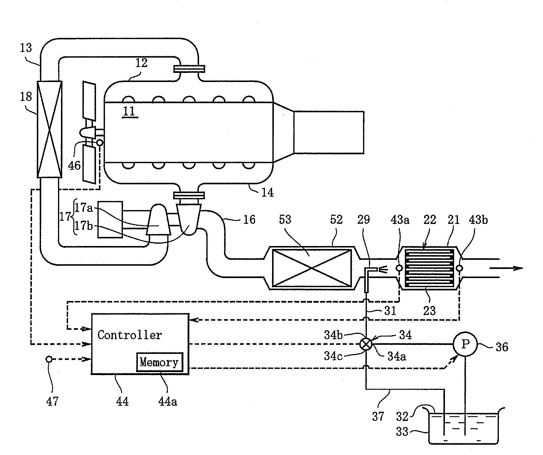
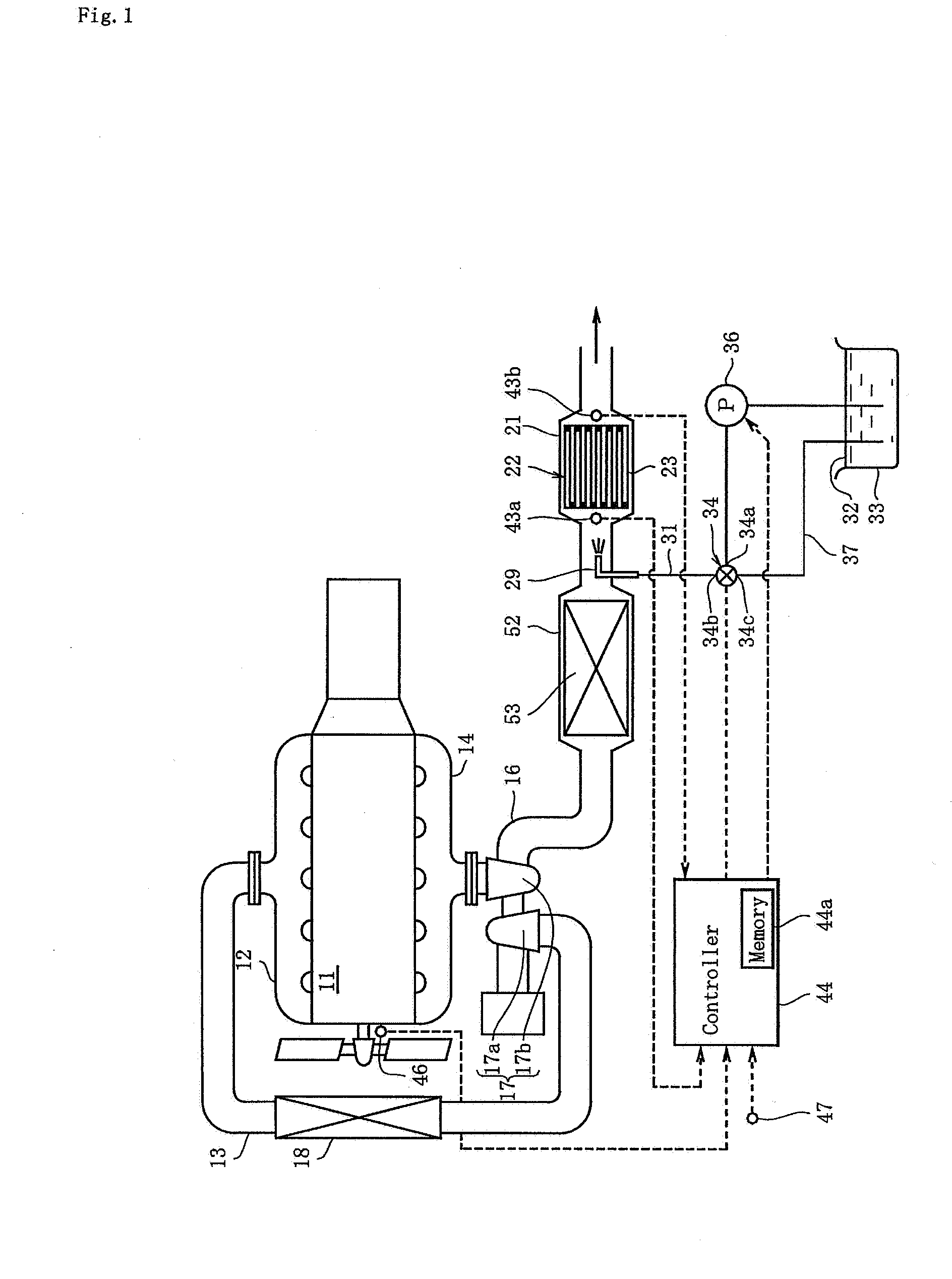
[0019]In the engine exhaust gas purifier comprising the selective reduction catalyst, the liquid injection nozzle which is provided at the
exhaust pipe on the exhaust-gas upstream side of the selective reduction catalyst and can inject the urea liquid toward the selective reduction catalyst, and the oxidation catalyst provided at the exhaust
pipe on the exhaust-gas upstream side of the selective reduction catalyst, when the urea liquid is injected from the liquid injection nozzle, the urea liquid is hydrolyzed and ammonia is generated, and the ammonia serves as a reducing agent for purifying NOx in the exhaust gas by the selective reduction catalyst, so that the amount of NOx emitted into the atmosphere can be reduced. On the other hand, if a particle-state
solid matter such as
ammonium nitrate is deposited on the selective reduction catalyst, it might clog the fine holes in the wall, but oxidation of or the like in the exhaust gas in the oxidation catalyst allows the temperature of the exhaust gas to be raised, the temperature of the particle-state
solid matter deposited on the selective reduction catalyst to be burned, and the selective reduction catalyst to be regenerated.

