Acoustic impact detection and monitoring system

a monitoring system and acoustic impact technology, applied in the field of pipelines, can solve problems such as generating acoustic shocks in pipelines

Active Publication Date: 2009-01-01
GENERAL ELECTRIC CO
View PDF38 Cites 47 Cited by
  • Summary
  • Abstract
  • Description
  • Claims
  • Application Information

AI Technical Summary

Benefits of technology

[0014]The historical data mining enabled by the present invention also enables ongoing incident trending and risk assessment to establish mitigati

Problems solved by technology

A sufficiently large impact from an excavator, a drill, or other object on the pipeline, or an ex

Method used


Image

  • Acoustic impact detection and monitoring system
  • Acoustic impact detection and monitoring system

Examples


Embodiment Construction

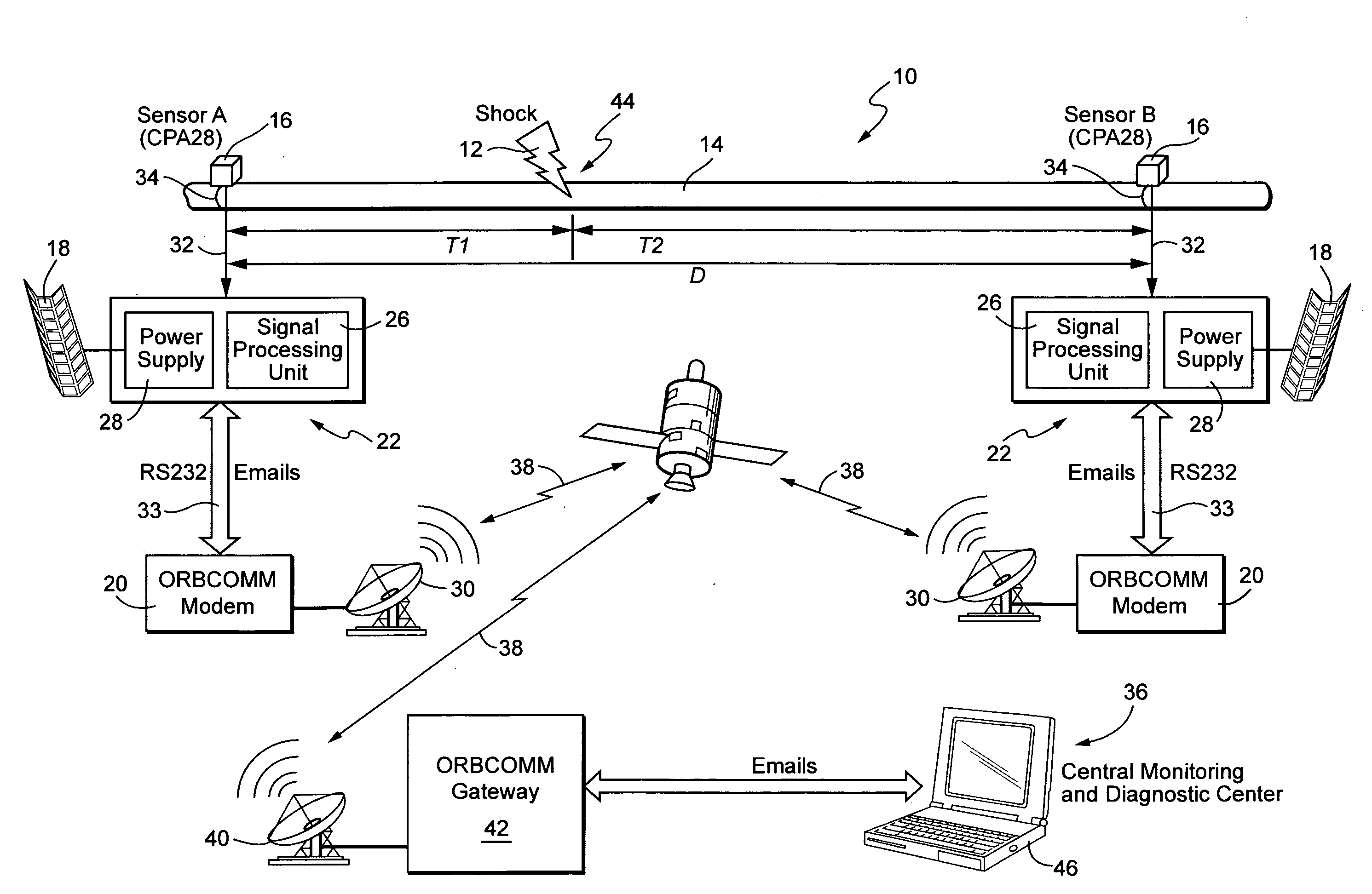
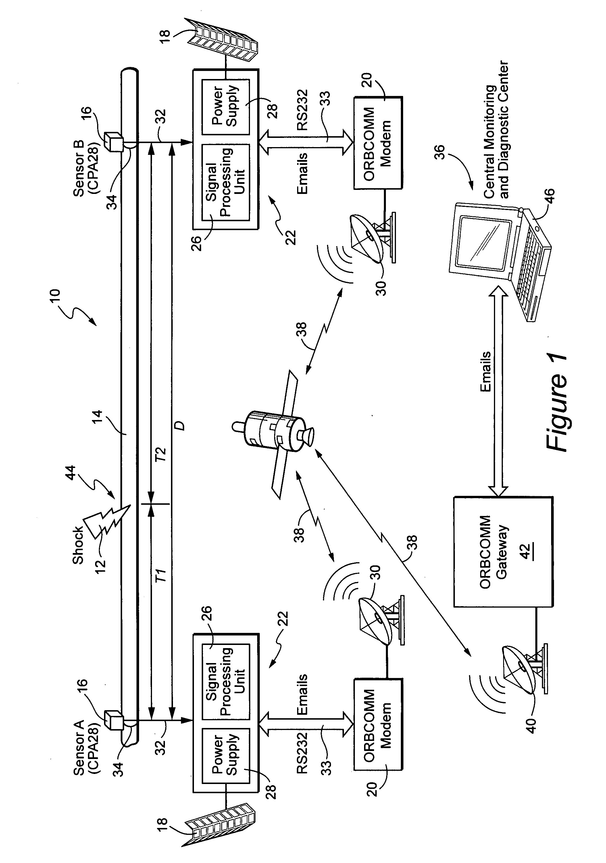
[0016]FIG. 1 is a schematic drawing showing an overview of one embodiment of a monitoring system 10 according to the present invention for detecting and locating third party shocks or impacts 12 to a pipeline 14. The system 10 detects and locates such impacts 12 through a series of hydrophone sensors 16, which are attached to pipeline 14 without the need for tapping.

[0017]At each sensor location, there are four basic components. They include a hydrophone sensor 16, power elements 18, communications equipment 20 and a corresponding sensor station 22. Each component is designed to perform in a wide spectrum of operating environments.

[0018]Preferably, the system 10 includes a hydrophone sensor 16 and a corresponding sensor station 22 at each of a series of locations along the pipeline 14. The spacing of each hydrophone 16 and corresponding sensor station 22 is selected to maximize sensor spacing without reducing system performance and reliability. Preferably, each sensor station 22 con...


PUM


Abstract

A system is disclosed for detecting and locating harmful impacts to pipelines using sensors placed along the pipeline. The exact spacing of sensors is site specific and is set with the goal of maximizing sensor spacing without reducing system performance and reliability. At each sensor location, preferably there are four basic components, i.e., a hydrophone, solar power components, and data processing and communications equipment. Each hydrophone directly measures the acoustic noise fluctuation in a pipe section, which propagates at long distances in the pipeline at the specific speed of sound for the particular type of pipe. If specific signal parameters exceed a programmed threshold, a detection message is generated and transmitted via a communications link to a central monitoring and diagnostic center.

Description

BACKGROUND OF THE INVENTION[0001]The present invention relates to pipelines, and more particularly, to a system for improving pipeline safety by detecting and locating third party impacts to a pipeline that may cause damage to the pipeline and informing operators about the third party impacts in a timely fashion.BACKGROUND OF THE INVENTION[0002]Damage from third party impacts to pipelines is considered the number one cause of pipeline failures. Pipeline operators need to know about pipeline impact events in order to investigate and determine appropriate responses to such events. With real time knowledge of such an event, a pipeline operator is more likely to be able to reach the site of the damage before the third party has left and is more likely to recover damages from the third party. Such knowledge also enables operators to effect timely repairs to any damage that, if left untreated, could lead to future failures with potentially much greater financial, safety and environmental ...

Claims


Application Information

Patent Timeline
IPC IPC(8): G08B21/00G01H17/00
CPCF16L55/00G07C3/08G01H3/12F16L2201/30
Inventor ALLISON, PETER S.CHASSAING, CHARLES E.LETHCOE, BRYAN
Owner GENERAL ELECTRIC CO
Why Eureka
Try Eureka