Method and apparatus for depositing raised features at select locations on a substrate to produce a slip-resistant surface

a raised feature and surface technology, applied in the direction of welding/cutting media/materials, manufacturing tools, welding/soldering apparatus, etc., can solve the problems of costly injuries, difficult or even hazardous locations for personnel and/or motor vehicles to move across, and the presently available non-skid materials have some negative aspects

Active Publication Date: 2009-01-01
OHIO GRATINGS
View PDF34 Cites 17 Cited by
  • Summary
  • Abstract
  • Description
  • Claims
  • Application Information

AI Technical Summary

Benefits of technology

[0010]Accordingly, it is an object of the present invention is to provide an improved metho...

Problems solved by technology

In certain industrial settings there are many locations that are difficult or even hazardous for personnel and/or motorized vehicles to move across due to materials that may coat the floor.
If no precautions are taken, slips and falls may occur to personnel that can lead to costly injuries.
However, the presently available non-skid materials all have some negative aspects.
Flame sprayed aluminum, paints, abrasives, and tapes often flake or wear-off, especially under high loads.
The use of hot rolled fabricated (carbon steel) materials is limited since they cannot be formed extensively.
If the plate requires further fabrication, however, such as bending, cutting, and/or shaping, it may result in a loss of the non-skid characteristics of the plate.
Moreover, the rolling of particles and flame-spraying techniques do not result in true metallurgical ...

Method used


Image

  • Method and apparatus for depositing raised features at select locations on a substrate to produce a slip-resistant surface
  • Method and apparatus for depositing raised features at select locations on a substrate to produce a slip-resistant surface
  • Method and apparatus for depositing raised features at select locations on a substrate to produce a slip-resistant surface

Examples


Embodiment Construction

)

[0027]Many of the fastening, connection, processes and other means and components utilized in this invention are widely known and used in the field of the invention described, and their exact nature or type is not necessary for an understanding and use of the invention by a person skilled in the art, and they will not therefore be discussed in significant detail. Furthermore, the various components shown or described herein for any specific application of this invention can be varied or altered as anticipated by this invention and the practice of a specific application of any element may already be widely known or used in the art by persons skilled in the art and each will likewise not therefore be discussed in significant detail. When referring to the figures, like parts are numbered the same in all of the figures.

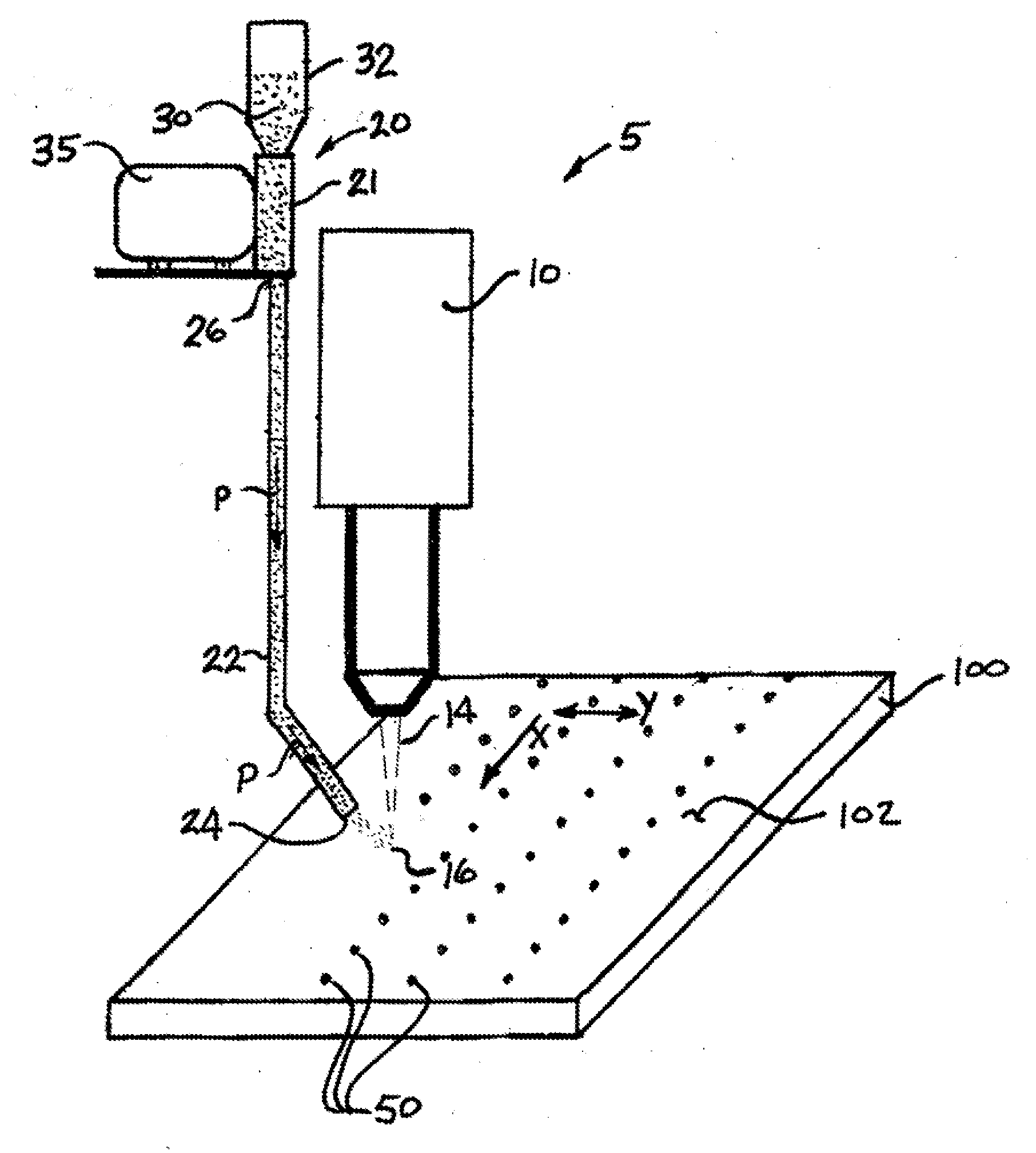
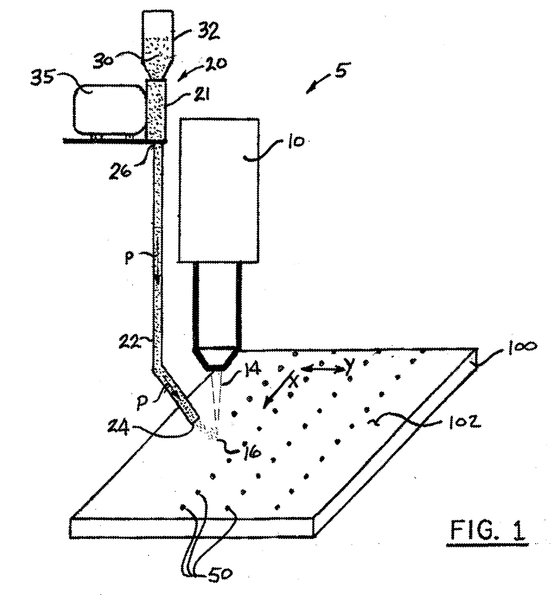
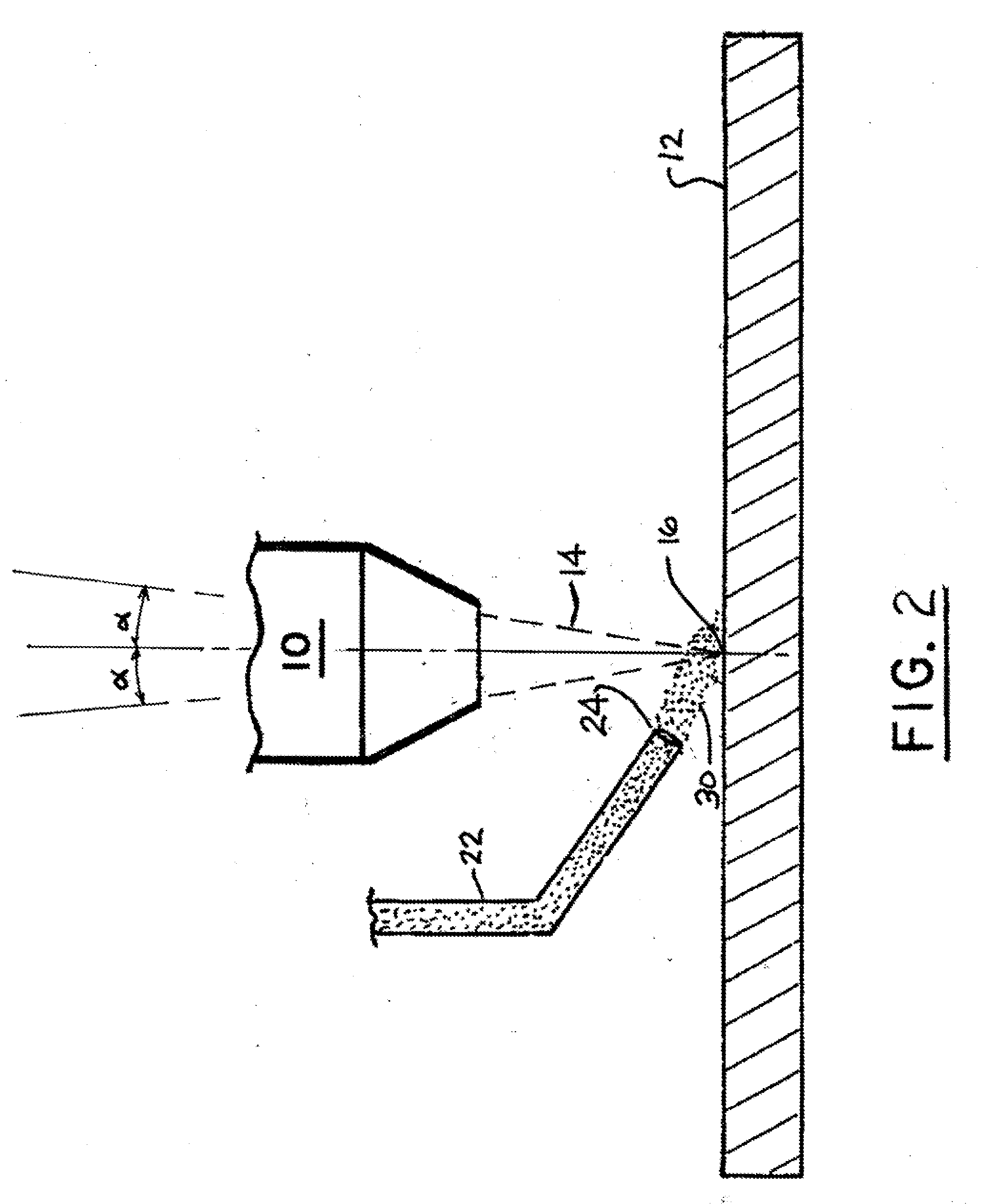
[0028]The goal in developing the process of this present invention for depositing a material on a metallic substrate in a manner to create a non-skid surface was to deve...


PUM

PropertyMeasurementUnit
Poweraaaaaaaaaa
Poweraaaaaaaaaa
Depthaaaaaaaaaa

Abstract

An improved apparatus and method for applying a plurality of raised features at select locations on a metallic substrate using a high-powered radiant energy source, such as a laser, in combination with powder metallurgy such that the resultant substrate surface exhibits increased slip-resistance resulting from the presence of the raised features on the substrate.

Description

BACKGROUND OF THE INVENTION[0001]The present invention is directed to the production of non-skid or slip-resistant material and more particularly to a method of producing a slip-resistant substrate by deposition of raised features of a compatible or dissimilar materials at select locations on the substrate surface by using a high power radiant energy source, such as a laser, an electron beam, plasma transfer arc, infrared lamps and the like, and a substrate including the same thereon.[0002]In certain industrial settings there are many locations that are difficult or even hazardous for personnel and / or motorized vehicles to move across due to materials that may coat the floor. Such materials include water mud, snow, blood, inks, oil, chemicals, and other slippery substances. If no precautions are taken, slips and falls may occur to personnel that can lead to costly injuries.[0003]In order to reduce the chances of slips and falls, many propose to alter the surfaces to increase tractio...

Claims


Application Information

Patent Timeline
IPC IPC(8): B23K26/06
CPCB23K26/0078B23K35/0244B23K26/34B23K26/3206B23K26/3213B23K26/322B23K26/3226B23K35/0255B23K35/286B23K35/302B23K35/3033B23K35/3053B23K35/308B23K35/32B23K35/325B23K35/3601B23K35/3602B23K35/386B23K26/1411B23K26/32B23K26/144B23K26/3584B23K2103/04B23K2103/05B23K2103/08B23K2103/10B23K2103/12B23K2103/14B23K2103/18B23K2103/26B23K2103/50B23K2103/52
Inventor LENTZ, JAMES
Owner OHIO GRATINGS
Why Eureka
Try Eureka