
Efficient seismic data acquisition with source separation

a source separation and seismic data technology, applied in seismic energy generation, seismicology, instruments, etc., can solve the problems of not capturing, many recording systems may also require additional time for a system reset, and the vibration has become the weak link in achieving efficient field operations. , to achieve the effect of reducing crosstalk

Active Publication Date: 2009-01-08
SERCEL INC
View PDF32 Cites 105 Cited by
  • Summary
  • Abstract
  • Description
  • Claims
  • Application Information

AI Technical Summary

Benefits of technology

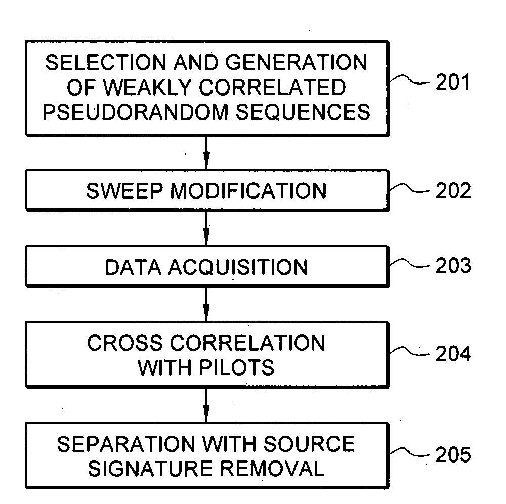
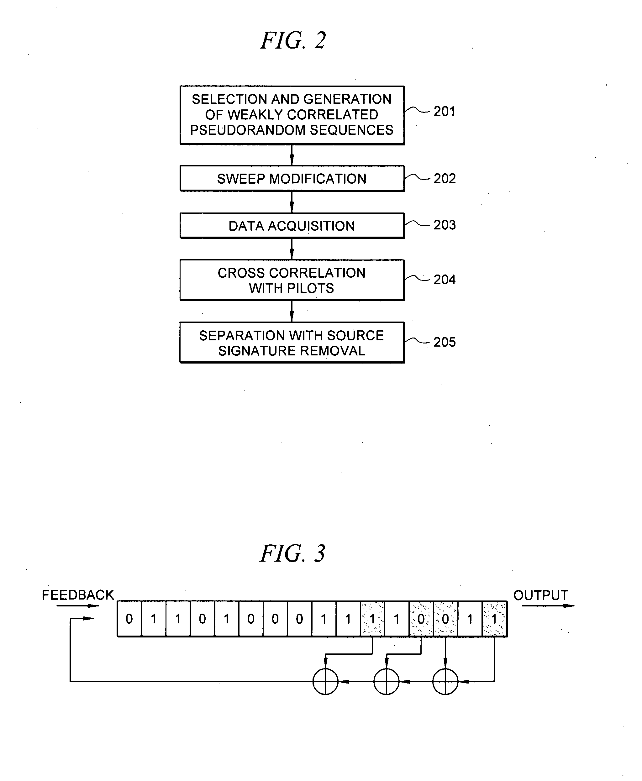
[0021]In accordance with another aspect of this invention, there is provided a method wherein the step of modifying the sequences to minimize crosstalk further comprises the steps of (1) sampling the weakly correlated pseudorandom sweep sequences: (2) generating the target spectrum; (3) reshaping the weakly correlated pseudorandom sequences by use of digital filtering; (4) computing cross-correlations between the various weakly correlated pseudorandom sequences and autocorrelations of the sequences; (5) decoupling the weakly correlated pseudorandom sequences; (6) performing level compression of the weakly correlated pseudorandom sequences; (7) filtering the weakly correlated pseudorandom sequences for high frequency noise; (8) computing autocorrelations of the sequences and cross-correlations between the various weakly correlated pseudorandom sequences: and (9) resampling the weakly correlated pseudorandom sequences.
[0022]In accordance with another aspect of this invention, there is provided a method for which the weakly correlated pseudorandom sequences are reshaped using the formula Target (x)=g1(x)g2(x) where g1(x) is (x / F1)2{[1−(x / F1)2]2+1.414*(x / F1)2}−0.5 and g2(x) is 1 for x less than or equal to F2 and is ((1+cos((x−F2) / (F3−F2)*π)) / 2)2 for x between F2 and F3, zero for x greater than F3, where F1=5, F2=100, and F3=150.

Problems solved by technology

The conventional method has a number of shortcomings some of which include: 1) poor source control; 2) harmonic distortion emissions by the vibrators; 3) intra-array statics because the vibrators are at different elevations or variations in the near surface that can affect source coupling to the earth; 4) spatial resolution issues due to array effects and limitation in source effort because of economic constraints; 5) control and synchronization problems associated with the use of multiple sources; and 6) mixed-phase data produced by the correlation process.
As a result, the vibrators have become the weak link in achieving efficient field operations.
Many recording systems may also require additional time for a system reset after each record.
HFVS-methods have some technical drawbacks including: 1) low frequency noise in the inverted records because of an absence of low frequencies in the source signal; 2) not capturing all harmonic energy produced in the measured source signal; 3) a large data volume; 4) poor quality control because uncorrelated data is used (“shooting blind”); and 5) source outputs using phase offset encoding, resulting in highly correlated source signals that require reliable phase encoding for good separation.
With the Continuous HFVS method, there is a high potential for problems associated with crosstalk between segments.
Second, the source-to-earth coupling problem is generally nonlinear.
While the measured source signal is helpful, it does not completely characterize or measure all the radiated harmonic energy.
Third, the source-to-earth coupling may change as the vibrator compacts the earth during the sweep or sweep segments.
This compacting may cause the travel time from the vibrator to the receiver to deviate slightly from sweep to sweep or from sweep segment to sweep segment.
Because phase encoding methods assume that the transmission path will remain constant between sweeps or sweep segments, data separation may be compromised.
Fourth, with Continuous HFVS there is an increase in the potential for problems associated with this residual harmonic energy from a later sweep segment interfering with deep reflection events from an earlier segment.
Finally, for Continuous HFVS the assumption that sweep segment length exceeds the two-way travel time to the deepest reflector of interest does not guarantee residual harmonic energy will not cause interferences between sweep segments.
While superposition and linearity assumptions may work with model data, these assumptions fail to simulate the real impact of residual harmonic energy.
Further, the accepted industry guideline for crosstalk between the separated source signals to fall below −40 dB is demanding.
The cost of seismic surveys depends heavily on the time required to collect the data.
Additionally, spreading out the spectral content of the sweep, rather than being concentrated for only a portion of the sweep, reduces the temporal peak energy of a given spectral element.
However, using up-sweeps, the harmonic energy is pushed into negative time and is generally not a problem because it is masked by strong arrivals at early times. For pseudorandom sweeps, harmonic energy is not well organized, but is dispersed across the record.
Most vibrators cannot deliver this high demand over an extended length of time and, as a result, the hydraulic system pressure drops well below its nominal differential supply pressure of 2,900 psi.
Lower system pressure results in lower force generation capability and higher distortion.
At the higher frequencies, the combined effect of fluid compressibility and fluid inertia create inefficiency in the system that requires higher flow to sustain a high force output from the vibrator.

Method used


Image

  • Efficient seismic data acquisition with source separation
  • Efficient seismic data acquisition with source separation
  • Efficient seismic data acquisition with source separation

Examples


Embodiment Construction

[0046]As used herein, “a” or “an” means one or more than one.

[0047]The methods and apparatus of the present invention will now be illustrated with reference to FIGS. 1 through 16D. It should be understood that these are merely illustrative and not exhaustive examples of the scope of the present invention and that variations which are understood by those having ordinary skill in the art are within the scope of the present invention.

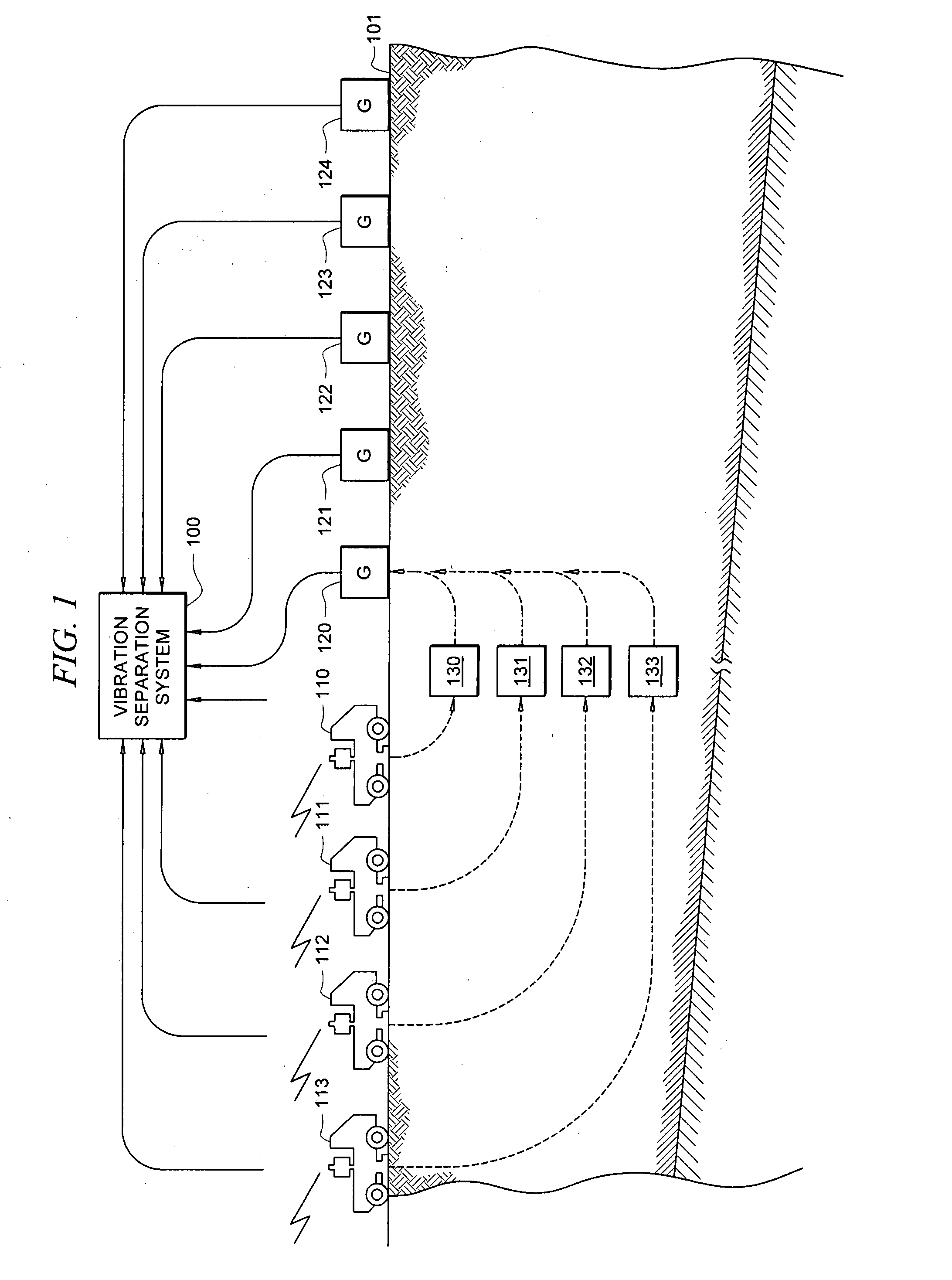
[0048]Looking first to the exemplary survey shown in FIG. 1, four vibrators 110, 111, 112, and 113 are placed at the surface of the earth 101. Vibrators 110, 111, 112, and 113 are conventional truck-mounted vertical P-wave vibrators; however, it is understood that other vibrators, such as horizontal shear-wave vibrators used for 9-C data sets, may be utilized. In this example vibrators 110, 111, 112, and 113 are spaced close to one another and collinear at a distance of about 40 feet from one another; however, the deployment of the vibrators may vary widel...


PUM


Abstract

A method for the simultaneous operation of multiple seismic vibrators using unique modified pseudorandom sweeps and recovery of the transmission path response from each vibrator is disclosed. The vibrator sweeps are derived from pseudorandom binary sequences modified to be weakly correlated over a time window of interest, spectrally shaped and amplitude level compressed. Cross-correlation with each pilot signal is used to perform an initial separation of the composite received signal data set. Recordings of the motion of each vibrator are also cross-correlated with each pilot, windowed, and transformed to form a source cross-spectral density matrix in the frequency domain useful for source signature removal and for additional crosstalk-suppression between the separated records. After source signature removal in the frequency domain an inverse transform is applied to produce an estimate of each source-to-receiver earth response in the time domain. The method has application to both land and marine geophysical exploration.

Description

TECHNICAL FIELD[0001]This invention relates generally to the field of seismic exploration, and more particularly, to methods for generating and processing simultaneous vibrator data.[0002]BACKGROUND OF THE INVENTION[0003]Geophysical prospectors have found seismic vibrators to be useful signal sources for imaging the earth. Conventional seismic acquisition in the past generally employed multiple vibrators acting together and initiated simultaneously to form a source array. In land-based operations, the vibrators are positioned at a source location and synchronized to the same pilot sweep signal. Once activated, the vibrators generate a sweep that typically lasts between five and twenty seconds and typically spans a predetermined range of frequencies. A recording system that is connected to a plurality of receivers, typically geophones for land-based seismic exploration, is employed to receive and record the response data. For reflection seismology, the record length is typically set ...

Claims


Application Information

Patent Timeline
Patent Type & Authority Applications(United States)
IPC IPC(8): G01V1/36
CPCG01V1/005G01V2210/127G01V1/37
Inventor SALLAS, JOHN J.GIBSON, JOHN B.
Owner SERCEL INC
Learn More