
Carbon Nanoflake Compositions and Methods of Production

a carbon nanoflake and composition technology, applied in the field of carbon nanostructure compositions, can solve the problems of less than ideal for research studies and practical applications, and the graphite plate cannot be oriented on a surface, and achieve the effects of novel morphology, and improving the uniformity of heigh

Inactive Publication Date: 2009-01-08
COLLEGE OF WILLIAM & MARY
View PDF5 Cites 9 Cited by
  • Summary
  • Abstract
  • Description
  • Claims
  • Application Information

AI Technical Summary

Benefits of technology

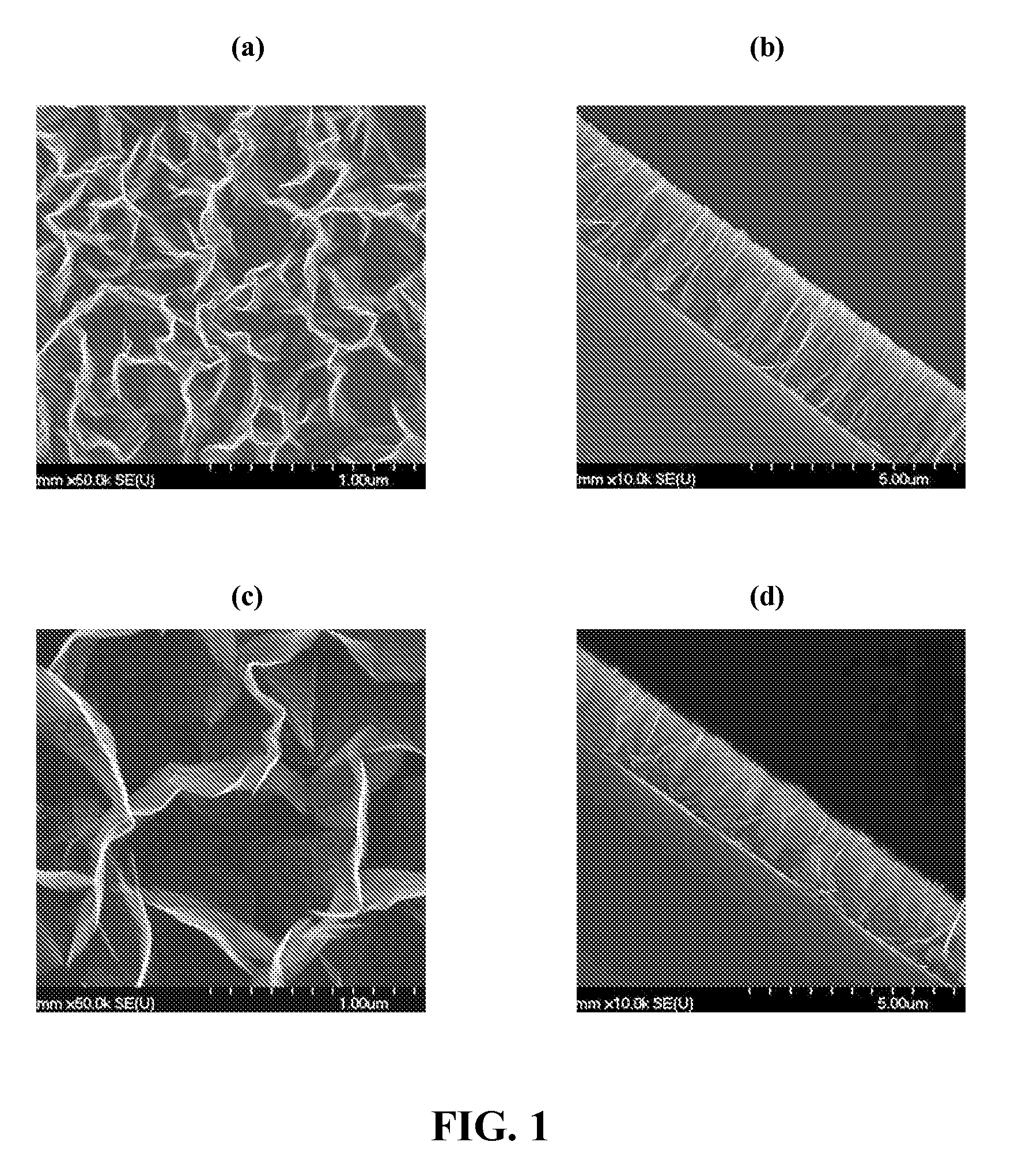
[0007]Herein we describe novel compositions and morphologies of carbon nanoflakes (CNF) and methods for making CNF using a radio frequency plasma enhanced chemical vapor deposition (RF-PECVD) process. Acetylene is used as a CVD source gas in the methods described herein. Prior art methods for making carbon nanoflakes via RF-PECVD processes contemplated using methane as a CVD source gas, and additionally contemplated the use of low concentrations of acetylene, at high temperatures, as a CVD source gas. Herein we describe the use of high concentrations of acetylene in the CVD source gas, which permits the desired nanoflake deposition at a reduced temperature range of 500° C. to 700° C. Under these conditions, carbon nanoflake growth can reach 15 μm per hour, a nearly ten-fold improvement over the growth rate using prior art methods. Additionally, the resulting nanoflakes have novel morphology, with enhanced uniformity of height, reduced packing density, and a more vertical orientation. Electron emission properties are improved, and the nanoflakes grown with this method, typically ½ nm-5 nm in thickness, are more robust. Importantly, this method consumes less of the thermal budget in the processing of various devices, potentially improving durability and performance.

Problems solved by technology

While this process has had some success, it still has the significant drawbacks, such as: (1) the graphite plates exist within a wide distribution of particles of different thicknesses which can not be separated; (2) the graphite plates are contaminated by the intercalation compounds used in the exfoliation process; and (3) the graphite plates cannot be oriented on a surface to provide large specific surface area structures and freestanding nanometer edges.
This makes them less than ideal for research studies and practical applications.

Method used


Image

  • Carbon Nanoflake Compositions and Methods of Production
  • Carbon Nanoflake Compositions and Methods of Production
  • Carbon Nanoflake Compositions and Methods of Production

Examples


Embodiment Construction

[0032]The embodiments of the present invention provide carbon nanoflake (CNF) compositions, methods of making these carbon nanoflake compositions, and methods of using the carbon nanoflake compositions. The CNF can come in a variety of forms as discussed in detail herein. Generally speaking, the CNF are sheet-like forms of graphite of varying dimensions.

[0033]Unless otherwise noted, the terms “a”, “an”, or “the” are not necessarily limited to one and may refer to more than one. For example, “a carbon nanoflake” may refer to two or more carbon nanoflakes. Unless otherwise noted, the term “between” followed by a number range is inclusive of the endpoints. For example, the phrase “between 1 and 1000” means 1, 1000, and anything in between those two endpoints.

[0034]Methods of Making Carbon Nanoflakes

[0035]In some embodiments, radio frequency plasma enhanced chemical vapor deposition (RF-PECVD) may be used to form CNF with or without the use of nanoparticle lithography and with or withou...


PUM

PropertyMeasurementUnit
thicknessaaaaaaaaaa
thicknessaaaaaaaaaa
heightaaaaaaaaaa

Abstract

Novel compositions and morphologies of carbon nanoflakes are described, as well as methods for making carbon nanoflakes using a radio frequency plasma enhanced chemical vapor deposition (RF-PECVD) process. Acetylene is used as a CVD source gas. By utilizing high concentrations of acetylene in the CVD source gas at relatively low temperatures, carbon nanoflake growth rate and robustness are improved, and the resulting carbon nanoflakes have enhanced height uniformity.

Description

CROSS-REFERENCE TO RELATED APPLICATIONS[0001]This application claims the benefit of and priority to U.S. Provisional Patent Application Ser. No. 60 / 948,444, filed Jul. 7, 2007, the entire disclosure of which is incorporated by reference herein.STATEMENT REGARDING FEDERALLY SPONSORED RESEARCH AND DEVELOPMENT[0002]This invention was made with government support under Grant No. N00014-05-1-0749 awarded by the Office of Naval Research. The government has certain rights in the invention.FIELD OF THE INVENTION[0003]The field of the invention relates to compositions of carbon nanostructures, and methods of making and using these compositions.BACKGROUND OF THE INVENTION[0004]Graphite, diamond, diamond-like carbon, amorphous carbon, fullerenes, carbon nanotubes, and carbon nanofibers are attractive for their diverse forms and remarkable properties, and can have widespread applications in almost all mechanical, physical, chemical, electrochemical, microelectronic fields.[0005]Work has been do...

Claims


Application Information

Patent Timeline
Patent Type & Authority Applications(United States)
IPC IPC(8): B32B5/16H05H1/24
CPCB82Y30/00B82Y40/00Y10T428/2982C01B2204/04C23C16/26C01B31/0453C01B32/186
Inventor ZHU, MINGYAOMANOS, DENNIS M.OUTLAW, RONALD A.
Owner COLLEGE OF WILLIAM & MARY
Learn More