Electrochemical Cell

a technology of electrochemical cells and electrodes, applied in the direction of secondary cells servicing/maintenance, cell components, cell component details, etc., can solve the problems of wire breakage, material forming the terminals is corroded by charge or discharge current, and the attachment area is reduced, etc., to achieve high capacitance and high reliability

Inactive Publication Date: 2009-01-08
SEIKO INSTR INC
View PDF20 Cites 47 Cited by
  • Summary
  • Abstract
  • Description
  • Claims
  • Application Information

AI Technical Summary

Benefits of technology

[0009]It is an object of the present invention to solve the above problems and to provide an electrochemical cell having high reliability and high capacitance.

Problems solved by technology

However, demands for resistance to reflow soldering, reduction in the attachment area, and the like are increasing due to environmental concerns and miniaturization of the attached devices.
However, the material forming the terminals is corroded by charge or discharge current when contacting electrolyte such as a liquid.
As the corrosion proceeds, wire breakage may ultimately occur and hinder functioning.
However, microscopic pin holes may form since the film is obtained by depositing particles in each of these methods.
As a result, if the protective film does not have pin holes, satisfactory property would be realized over a long period of time.
However, if the protective film has pin holes, electrolyte may gradually permeate into the protective film and ultimately corrode the inner terminals thereby causing wire breakage in the terminals.
However, this would increase the time required for film formation and cause the electrochemical cell to be expensive.

Method used


Image

  • Electrochemical Cell
  • Electrochemical Cell
  • Electrochemical Cell

Examples


first embodiment

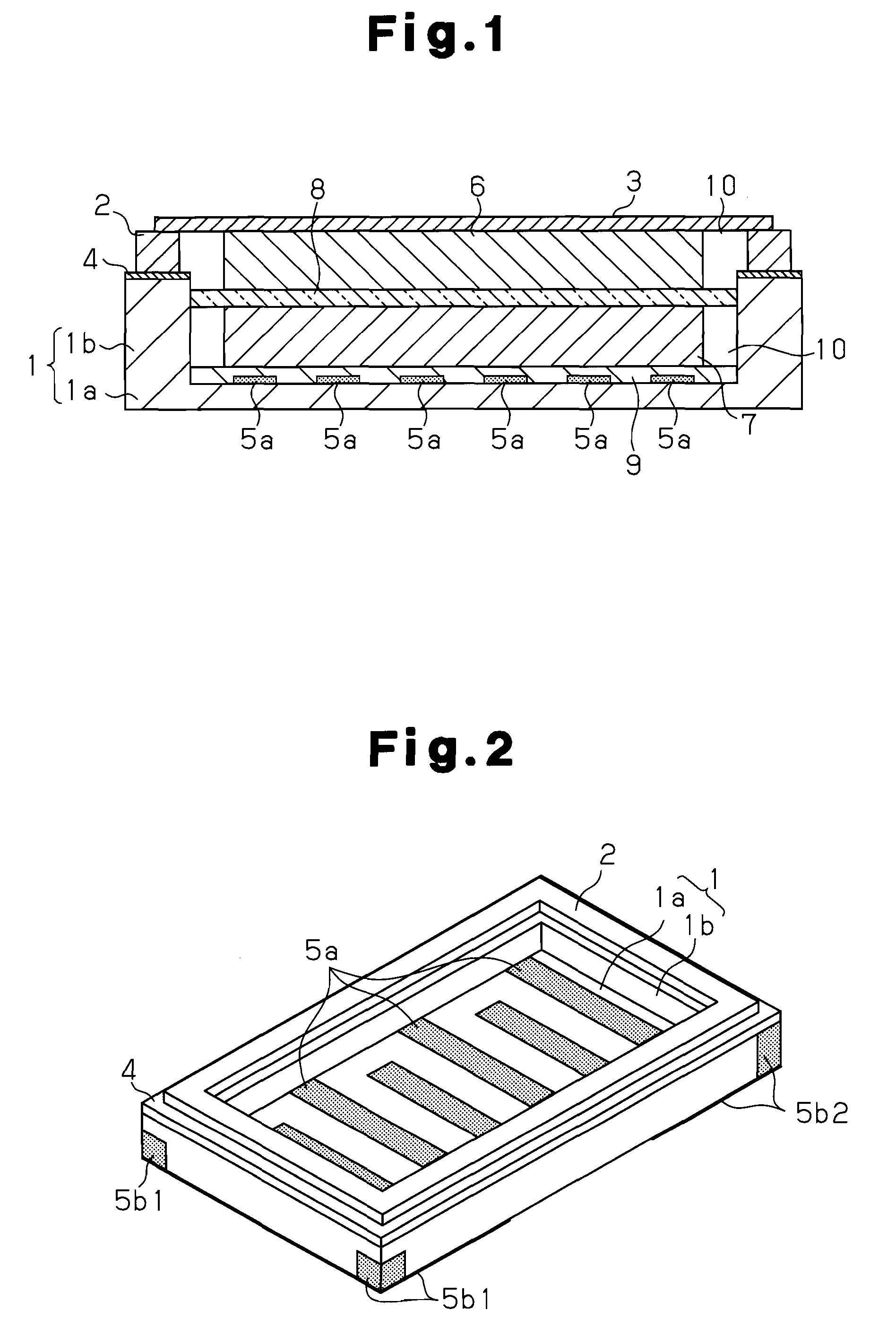
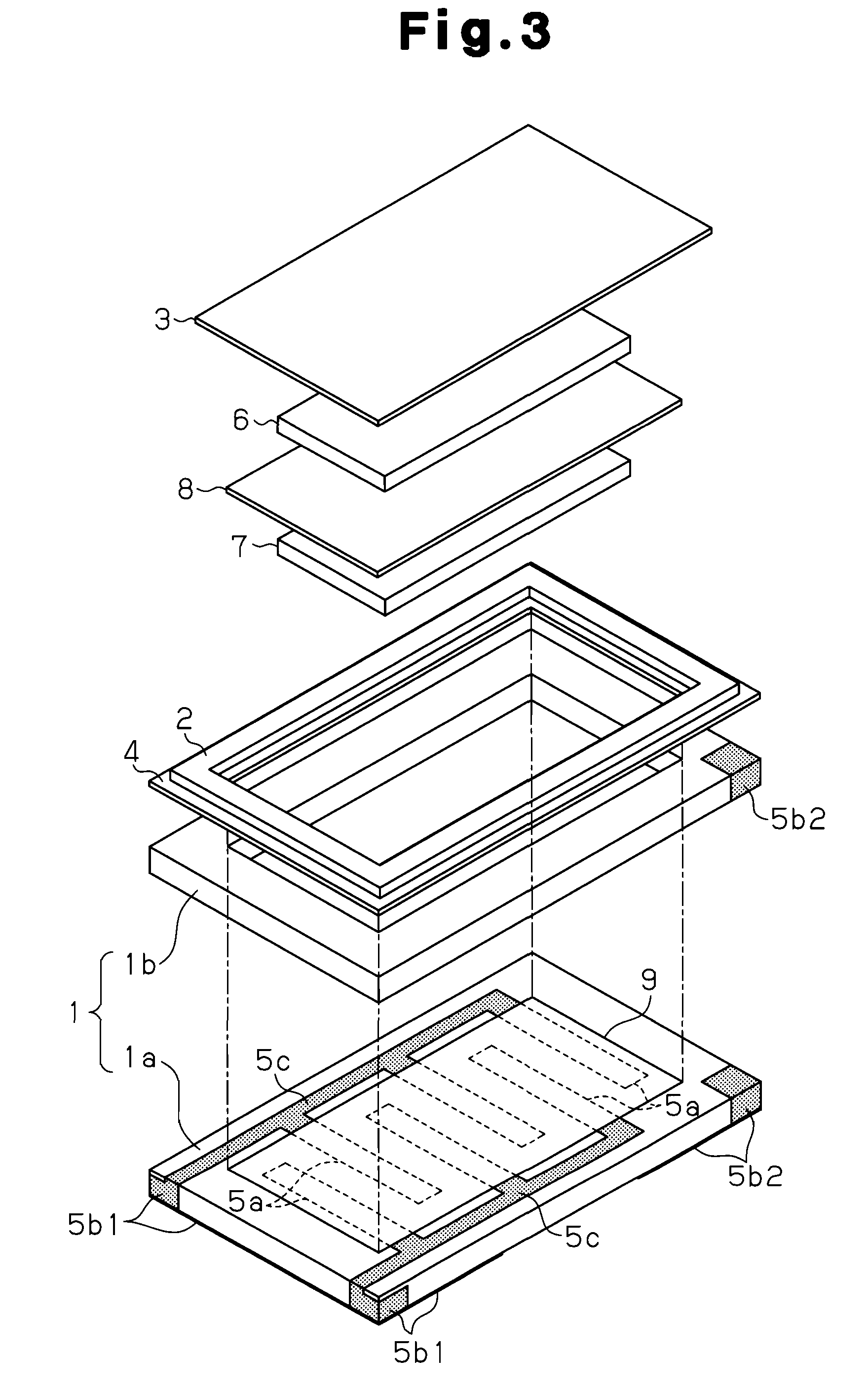
[0024]An electrochemical cell (electric double layer capacitor and battery) according to a first embodiment of the present invention will now be described according to FIGS. 1 to 4. FIG. 1 is a cross-sectional view of the electrochemical cell, FIG. 2 is a perspective view of a hollow container that forms the electrochemical cell, and FIG. 3 is an exploded view of the electrochemical cell.

[0025]As shown in FIG. 1, the electrochemical cell includes a hollow container 1. As shown in FIG. 2, the hollow container 1 is a box-shaped ceramic container having an open upper side and including a rectangular plate-shaped bottom portion 1a and a rectangular frame-shaped wall portion 1b formed along the periphery of the bottom portion 1a. Ceramic containing at least one selected from the group consisting of alumina, silicon nitride, zirconium, silicon carbide, aluminum nitride, mullite, and a composite of these materials is used for the hollow container 1. Heat resistance material such as glass a...

second embodiment

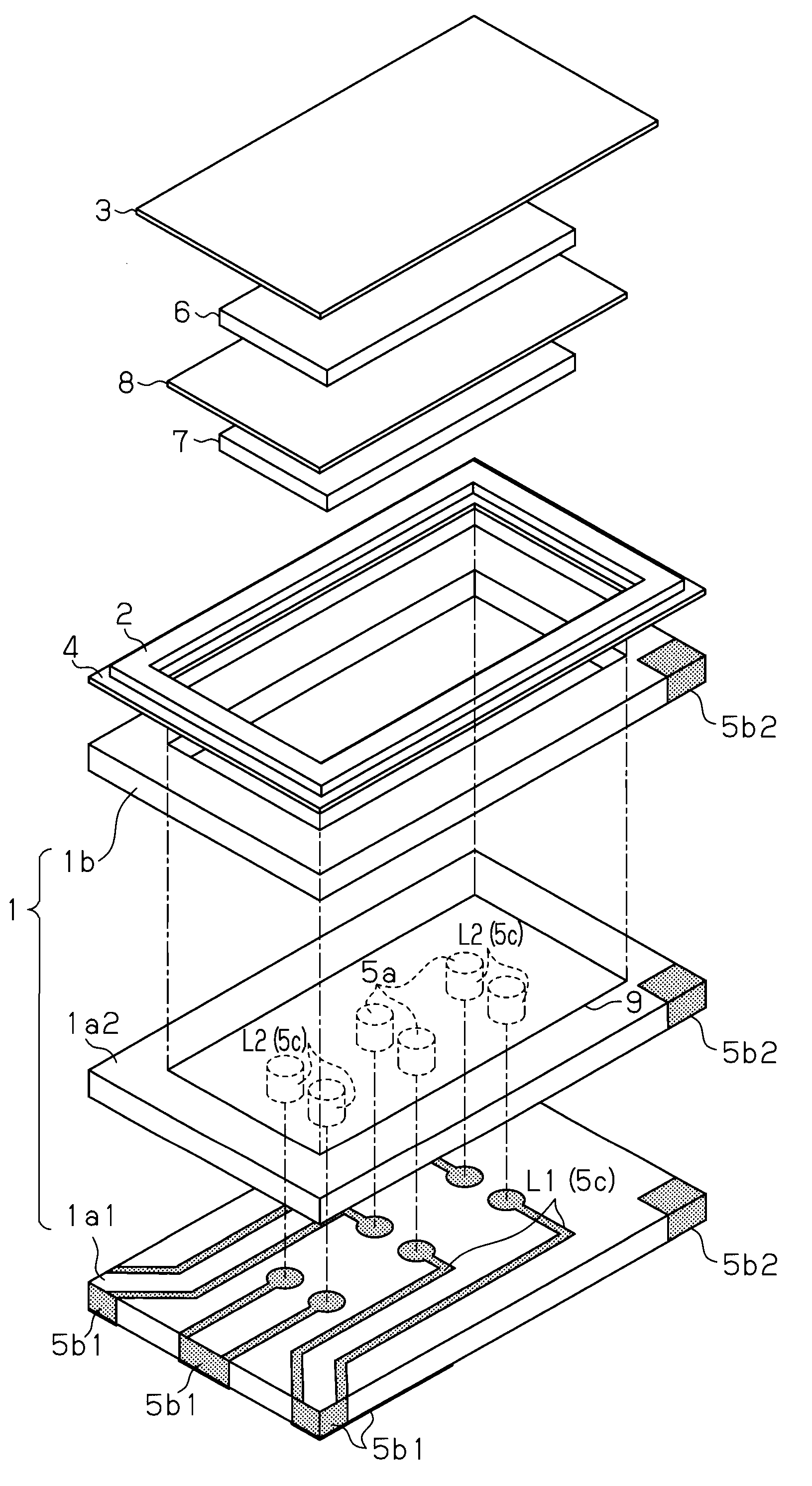
[0081]A second embodiment of the present invention will now be described according to FIGS. 5 to 8 focusing on the differences from the first embodiment. FIG. 5 is a cross-sectional view of the electrochemical cell of the second embodiment, FIG. 6 is a perspective view of a hollow container forming the electrochemical cell, FIG. 7 is a bottom view of the hollow container, and FIG. 8 is an exploded view of the electrochemical cell.

[0082]A hollow container 1 has a bottom portion formed by a first bottom portion 1a1 and a second bottom portion 1a2, which are rectangular plate-shaped, arranged from the bottom surface side, as shown in FIGS. 5 and 6.

[0083]As shown in FIGS. 7 and 8, a cathode outer terminal 5b1, which serves as common outer terminals corresponding to a cathode 7, and an anode outer terminal 5b2, which corresponds to an anode 6, are formed on the bottom surface of the first bottom portion 1a1. The cathode outer terminal 5b1 and the anode outer terminal 5b2 are extend from ...


PUM

PropertyMeasurementUnit
melting pointaaaaaaaaaa
length×width×thicknessaaaaaaaaaa
widthaaaaaaaaaa

Abstract

In an electrochemical cell including a cathode 7, an anode 6, electrolyte 10, a hollow container 1 accommodating these members, and terminals extending from the inside to the outside of the hollow container 1, the terminals include a plurality of inner terminals 5a formed on the inner surface of the hollow container 1, a cathode outer terminal 5b1 formed on the outer surface of the hollow container 1, and an inner layer wire 5c formed on the inner layer of the hollow container 1 for commonly connecting the plurality of inner terminals 5a to the cathode outer terminal 5b1.

Description

TECHNICAL FIELD[0001]The present invention relates to a surface attachable electrochemical cell.BACKGROUND ART[0002]A surface attachable electrochemical cell (electric double layer capacitor and battery) is used in a backup power supply for a clock function, a backup power supply for a semiconductor memory, and the like. In such compact electrochemical cells, the need for larger capacitance and larger current is reducing as progress is being made in the non-volatilization of semiconductor memories and the lowering of the power consumed by clock function elements. However, demands for resistance to reflow soldering, reduction in the attachment area, and the like are increasing due to environmental concerns and miniaturization of the attached devices.[0003]When attaching an electrochemical cell, solder cream etc. is applied in advance to the portion of a print substrate that is to undergo soldering. The electrochemical cell is attached on this portion. Alternatively, a small solder ba...

Claims


Application Information

Patent Timeline
Patent Type & Authority Applications(United States)
IPC IPC(8): H01M2/02H01G11/00H01G9/08H01M50/529H01G11/66H01G11/70H01G11/74H01G11/78H01G11/82H01M50/103H01M50/176H01M50/531H01M50/541H01M50/548H01M50/55H01M50/553H01M50/562H01M50/571H01M50/586
CPCH01G9/016H01M10/05H01G9/10H01G9/14H01G11/08H01G11/74H01G11/80H01G11/82H01M2/0207H01M2/26H01M2/30H01M2/34H01M10/425Y02E60/13H01G11/86H01M2/02H01M2/0202H01M2/0237H01M2/06H01G9/08Y02E60/10H01M50/531H01M50/553H01M50/586H01M50/562H01M50/55H01M50/176H01M50/548H01M50/103H01M50/109H01M50/571
Inventor ONODERA, HIDEHARUWATANABE, SHUNJIKON, MASAYA
Owner SEIKO INSTR INC
Why Eureka
Try Eureka