Catalytic Cracking Process Using Fast Fluidization for the Production of Light Olefins from Hydrocarbon Feedstock

a hydrocarbon feedstock and hydrocarbon cracking technology, which is applied in the direction of catalytic naphtha reforming, organic chemistry, hydrocarbon oil treatment products, etc., can solve the problems of limited production of light olefin compounds, high heat energy requirements, and difficult control of the composition of olefins, etc., and achieve high selectivity and high conversion rates

Active Publication Date: 2009-01-08
SK INNOVATION CO LTD
View PDF6 Cites 34 Cited by
  • Summary
  • Abstract
  • Description
  • Claims
  • Application Information

AI Technical Summary

Benefits of technology

[0030]According to the present invention, in the process of producing light olefin hydrocarbons from a hydrocarbon feedstock, for example, naphtha or kerosene, using a fluidized bed catalytic cracking process, the gas flow velocity and catalyst supply velocity, as the operation conditions of the riser for use in the catalytic cracking, are controlled, such that the flow regime of the riser is maintained as a fast fluidization regime. Thereby, it is possible to provide a flow regime effective for the selective production of light olefins such as ethylene and propylene at high conversion rates and high selectivity through maximization of the volume fraction of the catalyst in the riser.

Problems solved by technology

Further, light olefin compounds have been limitedly produced as a by-product of FCC (Fluid Catalytic Cracking) mainly for use in the production of gasoline.
However, it is not easy to control the composition of olefins using the present steam cracking technique, and as well, the reaction takes place at 800˜900° C. and thus a lot of heat energy is required.
However, FCC suffers because olefins are produced as the by-product.
However, these methods do not provide operation conditions for efficient use of the reaction product, in consideration of the properties of the catalytic cracking reaction.
However, the process disclosed in this patent cannot be applied to the catalytic cracking process of the present invention using a hydrocarbon feedstock, preferably naphtha or kerosene.
However, the additional development of processes for selectively producing light olefins, such as ethylene and propylene, from hydrocarbons that have high economic availability and may be used in great quantities as the feedstock, in particular, naphtha or kerosene, at high conversion rates and high selectivity is still urgently required.
However, in the reaction involving the use of the catalyst, such as the fluidized bed catalytic cracking process, the total amount of the catalyst positively affects the performance of the process.
In particular, since the catalytic cracking of the hydrocarbon compound is an endothermic reaction, a lot of heat is required.
However, there is no specific content related to a technique for realizing a high catalyst circulation rate necessary for the catalytic cracking process in the turbulent regime.

Method used


Image

  • Catalytic Cracking Process Using Fast Fluidization for the Production of Light Olefins from Hydrocarbon Feedstock
  • Catalytic Cracking Process Using Fast Fluidization for the Production of Light Olefins from Hydrocarbon Feedstock
  • Catalytic Cracking Process Using Fast Fluidization for the Production of Light Olefins from Hydrocarbon Feedstock

Examples


example 1

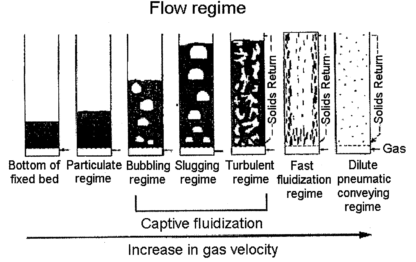
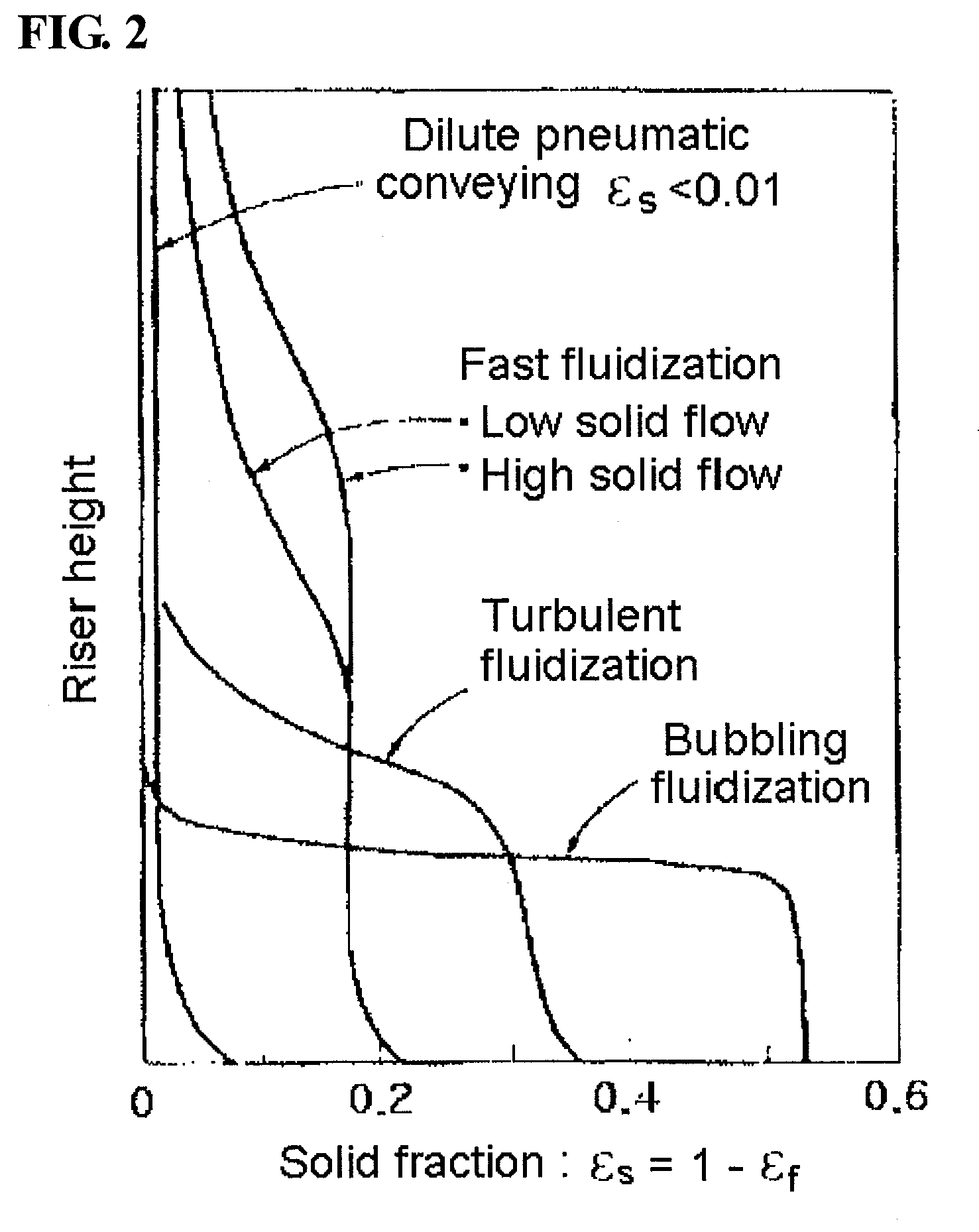
Fast Fluidization Regime

A. Fabrication of Cold Model

[0092]A cold model was fabricated in the same manner as in Comparative Example 1, as shown in FIG. 4.

B. Catalyst

[0093]The same catalyst as that used in Comparative Example 1 was used.

C. Test for Flow Regime

[0094]The test was conducted in the same manner as in Comparative Example 1. The velocity of the fluidization gas was 0.83 m / s, and the velocity of the catalyst to be circulated into the inlet of the lower portion of the riser was 7.7 kg / hr, corresponding to 33.6 kg / m2s in the riser. Under the above conditions, the pressure drop value was measured along the riser height, and thus the solid fraction was obtained (FIG. 6). In FIG. 6, the solid fractions were 0.092 and 0.049 at the ¼ point and ¾ point from the lower portion of the riser, respectively, the difference therebetween being 0.043. According to the definition of the present invention, the flow regime could be confirmed to be a fast fluidization regime.

example 2

A. Preparation of Catalyst

[0106]A catalyst was prepared in the same manner as in Comparative Example 2.

B. Treatment of Catalyst with Steam

[0107]The catalyst was treated with steam in the same manner as in Comparative Example 2.

C. Production of Light Olefin

[0108]In Example 2, a fluidized bed reaction system the same as in Comparative Example 2 was used, with the exception of the riser. As such, the riser had a height of 2.4 m and a diameter of 0.94 cm.

[0109]A feedstock having a composition the same as in Comparative Example 2 was used, and the feedstock had conditions of 150 g / hr and 400° C., the steam had conditions of 45 g / hr and 400° C., and the catalyst had conditions of 8400 g / hr and 725° C. In consideration of the sectional area of the riser, the catalyst was supplied in an amount of 33.6 kg / m2s (the same as that of the cold model of Example 1). Further, in order to efficiently circulate the solid catalyst in the interest of the properties of the test system, 60 L / hr of nitroge...


PUM

PropertyMeasurementUnit
boiling pointaaaaaaaaaa
sizeaaaaaaaaaa
sizeaaaaaaaaaa

Abstract

Disclosed is a catalytic cracking process for the production of light olefins from a hydrocarbon feedstock using fast fluidization, which is a preferred process for more efficiently increasing the production of light olefin hydrocarbons. According to this invention, a fast fluidization regime is applied to a fluidized bed catalytic cracking process of producing light olefins using zeolite, such that a volume fraction and distribution of the catalyst sufficient to induce the catalytic cracking reaction can be provided, thus effectively enhancing the production of light olefin hydrocarbons, in particular, ethylene and propylene, at high selectivity.

Description

TECHNICAL FIELD[0001]The present invention relates to a catalytic cracking process for the production of light olefins from a hydrocarbon feedstock using fast fluidization, and more specifically, to a catalytic cracking process for the production of light olefins from a hydrocarbon feedstock, in which the flow regime of a riser is maintained as a fast fluidization regime instead of a conventional dilute pneumatic conveying regime, thus more efficiently producing light olefin hydrocarbons.BACKGROUND ART[0002]These days, light olefins, in particular, light olefins such as ethylene or propylene, have been widely used in petrochemical industries. Generally, such light olefins have been mainly produced through steam cracking for thermally cracking (e.g., steam cracking) naphtha or kerosene in the presence of steam. Further, light olefin compounds have been limitedly produced as a by-product of FCC (Fluid Catalytic Cracking) mainly for use in the production of gasoline.[0003]The steam cra...

Claims


Application Information

Patent Timeline
Patent Type & Authority Applications(United States)
IPC IPC(8): C07C4/06
CPCC07C7/04C10G2400/20C10G2300/1044C10G2300/4093C10G2300/802C10G2300/1051C10G2300/301C07C11/02Y02P20/584C07C4/06C10G35/14
Inventor CHOI, SUNKIM, YONG SEUNGPARK, DEUK SOOKIM, SUK JOONKIM, JI MINKIM, HONG CHANOH, SEUNG HOONKIM, TAE JINCHOO, DAE HYUN
Owner SK INNOVATION CO LTD
Why Eureka
Try Eureka