Energized Fluid Motor and Components

a technology of fluid motors and components, applied in the direction of fluid couplings, servomotors, rotary clutches, etc., can solve the problems of reducing the energy available to move the piston to supply power, affecting the operation of the valve, so as to increase the density of the incoming air, increase the thrust, and increase the effect of thrus

Inactive Publication Date: 2009-01-15
COURTRIGHT GEOFFREY B
View PDF11 Cites 15 Cited by
  • Summary
  • Abstract
  • Description
  • Claims
  • Application Information

AI Technical Summary

Benefits of technology

[0043]The present invention further comprises a compressed air system. The compressed air is injected into the cylinder to move the piston and into the engine to detonate a fuel. The present invention further comprises a ducted fan. The present invention further comprises a motor that drives a hydraulic system. In an embodiment, the hydraulic drive uses conventional principles to provide forward or reverse rotation to the blades of the ducted fan. In an embodiment, a byproduct from a detonation in the engine is directed to the intake of the ducted fan. Introduction of byproducts provides a boost in thrust by increasing the density of the incoming air thereby making the ducted fan...

Problems solved by technology

The combustion of these fuels, however, presents environmental concerns about air pollution.
A disadvantage of the double acting steam engine is that the steam, due to entering the cylinder via the same port that the exhaust uses to exit, cools before it enters the cylinder, thus providing less energy available to move the piston to supply power.
The uniflow steam engine, however, operates with rapid short opening times of the inlet valves, causing fatigue and eventual breakdown of the valves.
An additional problem with existing steam engines is torque.
While a steam engine can provide maximum torque from a dead stop, if the load is too much for the piston, the piston breaks.
Incomplete combustion occurs when too little oxygen is supplied for too little time for the fuel to burn completely.
In incomplete combustion, the burn also produces numerous toxic by-products, such as carbon monoxide and nitrogen oxides.
Incomplete combustion is a problem because these by-products can be quite unhealthy and damaging to the environment.
In existing engines, “complete” burning is usually not achieved; even “near complete” fuel burning typically yields minor amounts of by-products.
The burning of a highly caloric fuel generally results in an incomplete burn producing toxic by-products.
In so doing, toxic by-products have the potential to enter the environment.
The main reason for the deliberate release of energy is that standard internal combustion engines a...

Method used


Image

  • Energized Fluid Motor and Components
  • Energized Fluid Motor and Components
  • Energized Fluid Motor and Components

Examples


Embodiment Construction

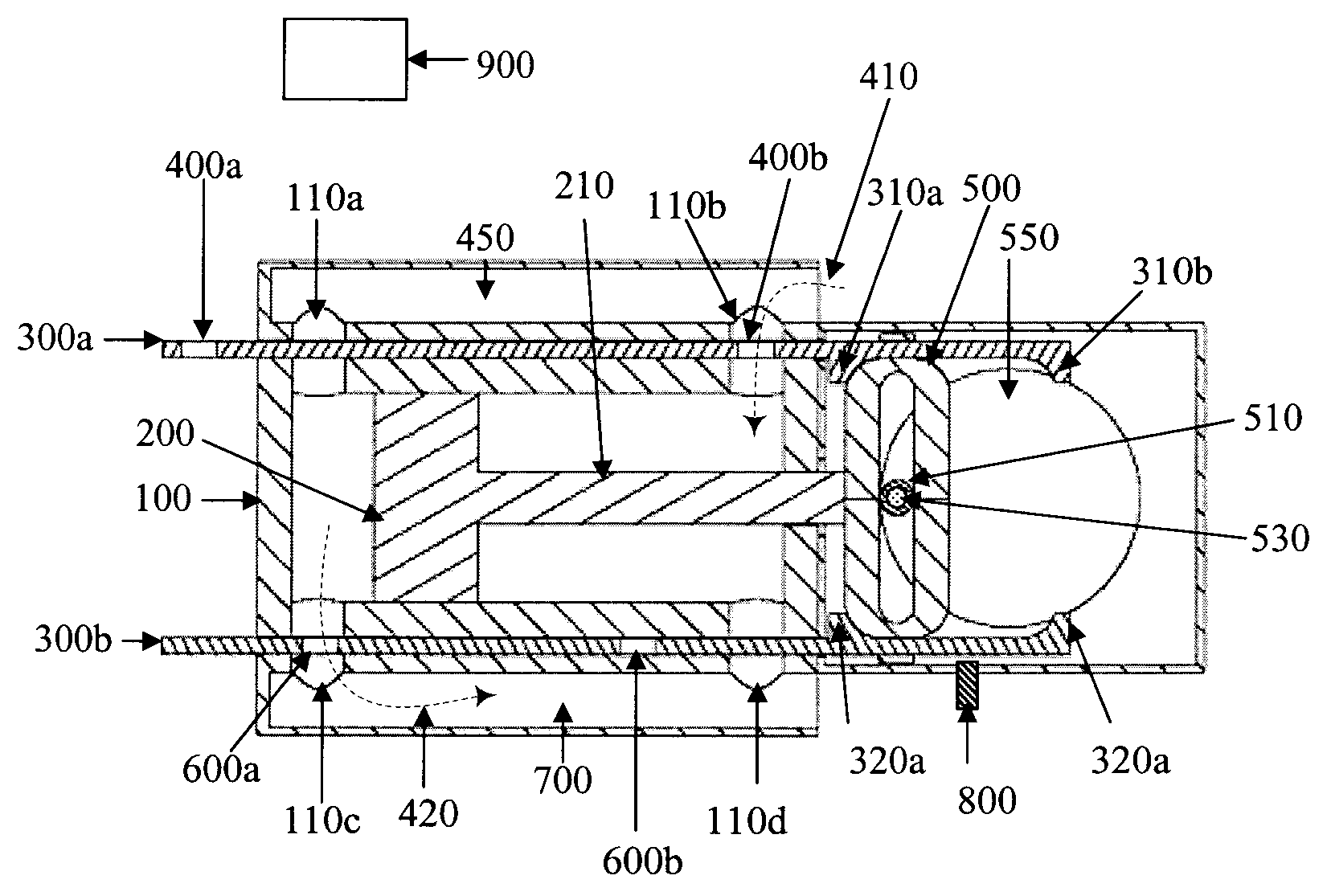
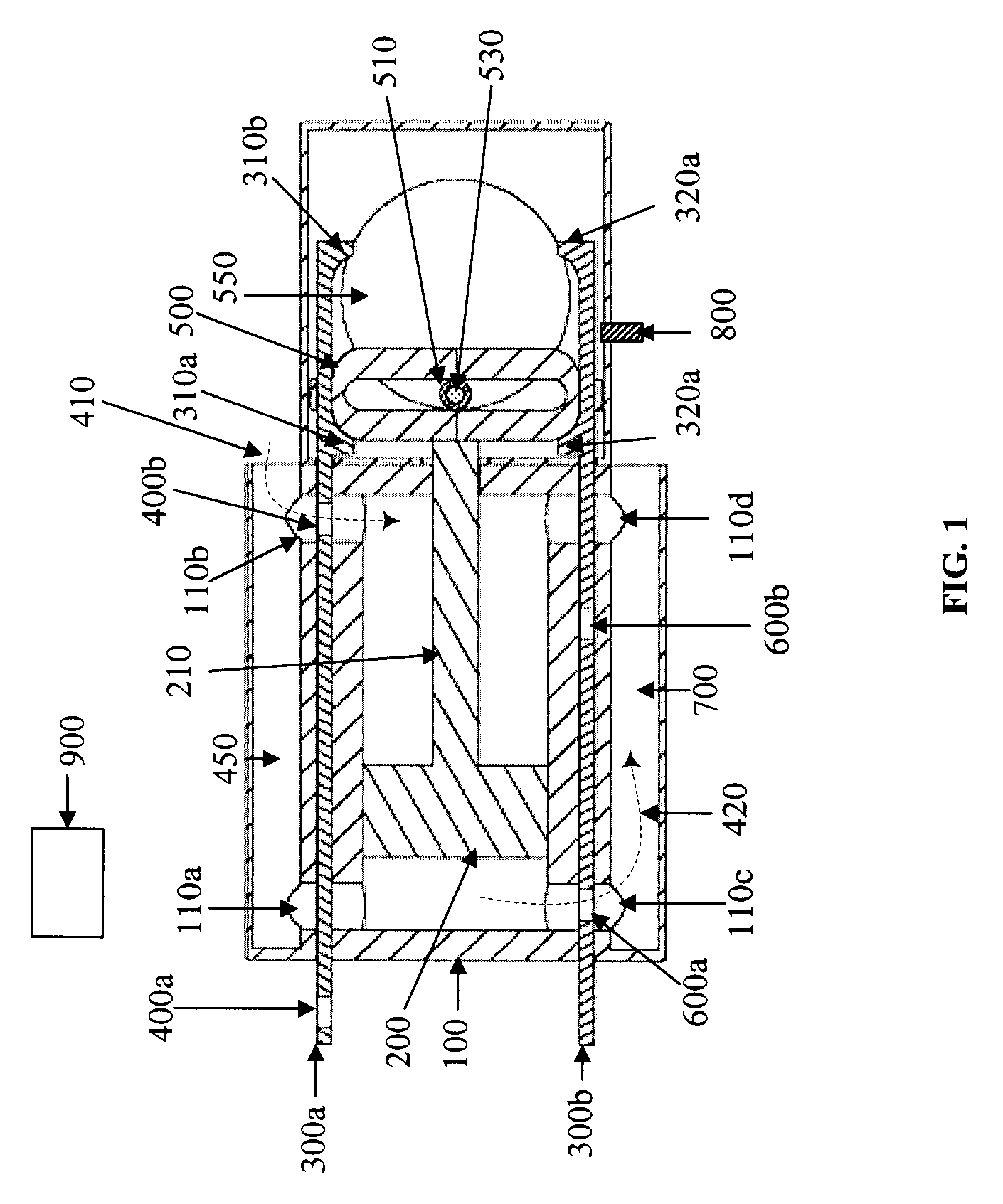
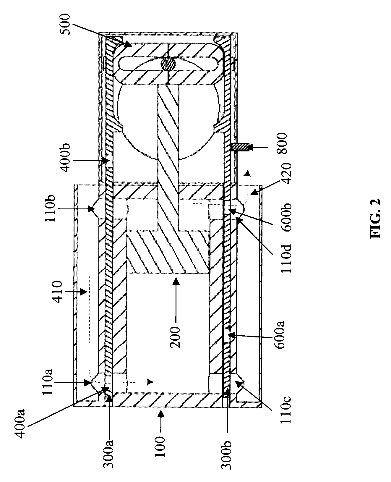
[0070]As depicted in FIG. 1, the motor of the present invention comprises at least one cylinder 100 enclosing a piston 200. The piston 200 comprises a piston shaft 210 that extends through an end wall of the cylinder 100. Optionally, the piston 200 has at least one ring. The piston 200 is slideable in the cylinder 100. The point of contact of the piston shaft 210 with the wall of the cylinder 100 comprises a seal and or at least one bearing. The size of the cylinder 100 and the length of the piston shaft 210 vary based upon application of the motor. The piston and cylinder are of any design and size acceptable for use in a motor. In an embodiment, a minimal length piston shaft 210 is used to provide higher acceleration.

[0071]In an embodiment, a first sliding bar 300a and a second sliding bar 300b are in communication with a wall of the cylinder 100. A side wall of the cylinder 100 comprises a first set of ports 110a 110b and a second set of ports 110c 110d. The first sliding bar 300...


PUM


Abstract

A motor comprising a least one piston slideable within a cylinder with a seal, a plurality of valves, means to determine the position of the valves and a head of the piston, means to select the ports in which to transfer energized fluid/exhaust in and out of the cylinder, and a scotch yoke. The cylinder comprising at least a first set of ports and a second set of ports. The ports disposed in a wall of the cylinder. The valves coupled and slideable to allow a selective transfer of an energized fluid in, and an exhaust out, of the cylinder via the ports. The scotch yoke operatively interacting with a crankshaft, the piston operatively connected to the scotch yoke such that, when the energized fluid moves the piston, torque is applied to the crankshaft, and the valves are repositioned to allow the energized fluid to enter the cylinder on the opposite side of the head of the piston and the exhaust to exit the cylinder.
An apparatus comprising a motor and an engine having a first fuel supplier supplying an oxidizer and a second fuel supplier supplying a dense fuel. The engine producing power to drive a ducted fan. The apparatus optionally comprising a hydraulic system.

Description

FIELD OF THE INVENTION[0001]The present invention relates to a motor and components and more specifically to the production and control of fluids for use in a cylinder / piston motor.BACKGROUND OF THE INVENTION[0002]Converting energy into useful work by driving a piston in a cylinder is well known. Pressure is used to push the piston contained in the cylinder. The piston is typically connected to a crankshaft by a rod extending from the cylinder. The movement of the piston converts the pressure into rotating mechanical energy.[0003]Most pistons move in a cylinder as a result of internal combustion, provided by the ignition of petrol, diesel fuel, oil, natural gas and the like to provide pressure. The combustion of these fuels, however, presents environmental concerns about air pollution.[0004]An alternative to internal combustion engines is the use of compressed air, steam or other hot gases to drive the piston. A type of steam engine is the double-acting steam engine, which has a cyl...

Claims


Application Information

Patent Timeline
IPC IPC(8): F15B11/00
CPCF01B9/023F02B75/24F01L23/00F01L7/04
Inventor COURTRIGHT, GEOFFREY B.
Owner COURTRIGHT GEOFFREY B
Why Eureka
Try Eureka