Invertebral spinal implant and method of making the same

a spinal implant and invertebral technology, applied in the field of spinal implant and method of making the same, can solve the problems of degeneration or damage to the inner disk of the vertebrae, and achieve the effects of optimizing the retention of osteogenic material, promoting bone growth, and promoting fusion of two adjacent vertebra

a spinal implant and invertebral technology, applied in the field of spinal implant and method of making the same, can solve the problems of degeneration or damage to the inner disk of the vertebrae, and achieve the effects of optimizing the retention of osteogenic material, promoting bone growth, and promoting fusion of two adjacent vertebra

US20090018659A1Inactive Publication Date: 2009-01-15MALININ THEODORE I

Image

  • Invertebral spinal implant and method of making the same
  • Invertebral spinal implant and method of making the same
  • Invertebral spinal implant and method of making the same

Examples


Embodiment Construction

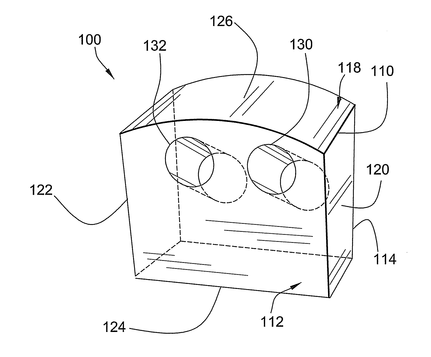
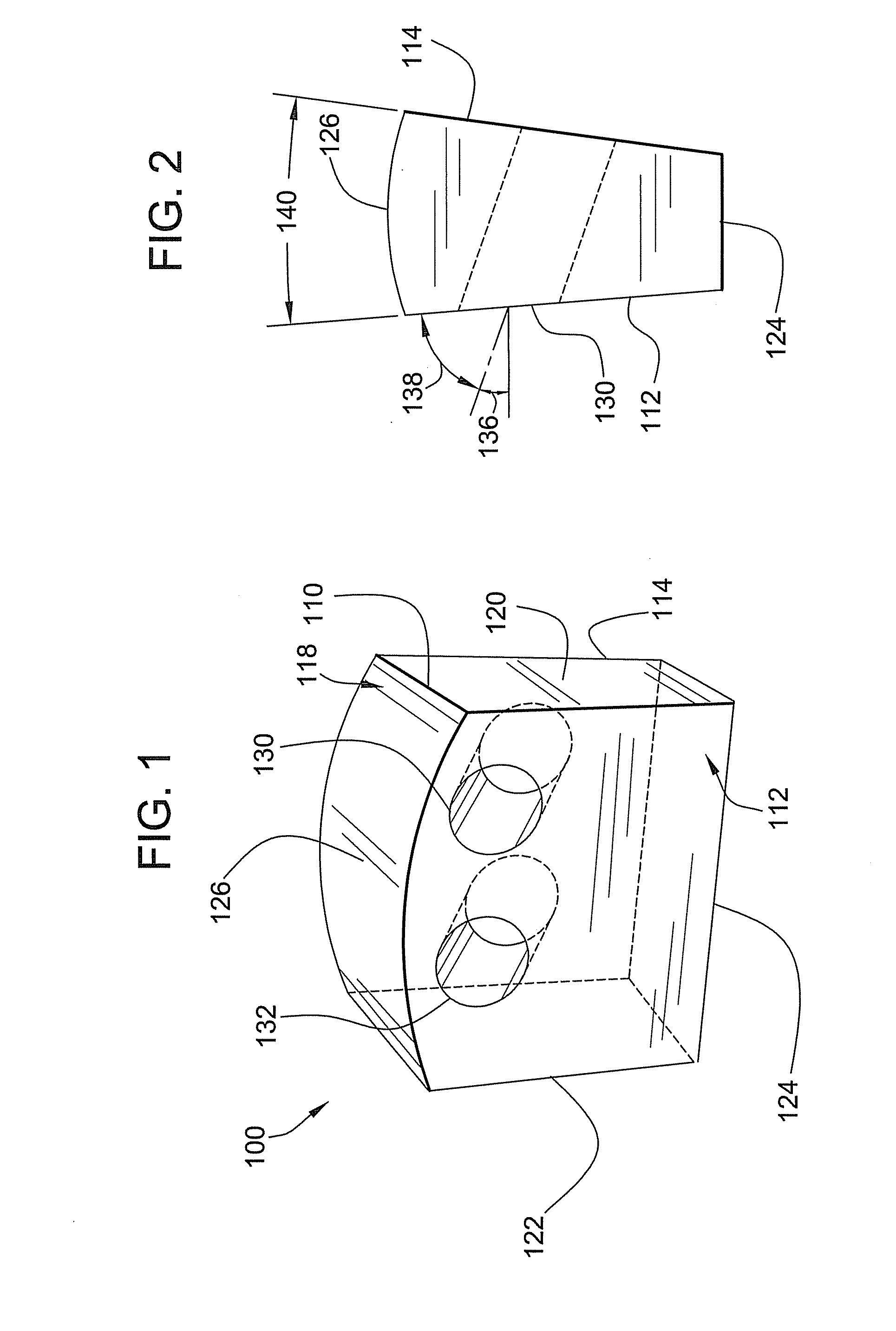
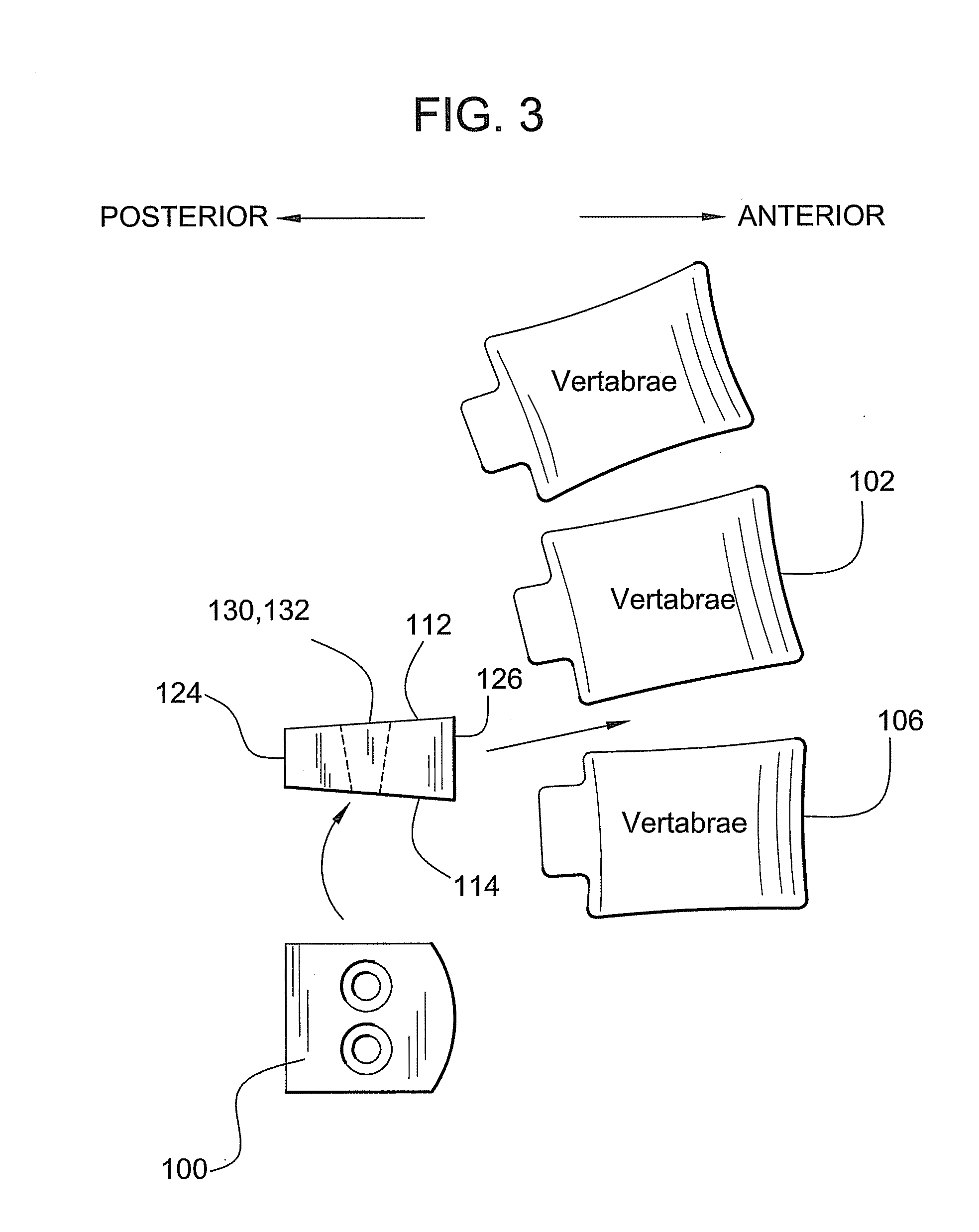
[0019]Now referring to the drawings, wherein like numbers refer to like elements, there is illustrated in FIGS. 1 and 2 an intervertebral implant 100 that can replace a damaged or ruptured intervertebral disk within the spinal column. The generally solid implant 100 can have a block-like shape including a generally flat body 110 including a first surface 112, an opposing second surface 114 and a peripheral surface 118 extending between the opposed first and second surfaces. In the illustrated embodiment, the intervertebral implant 100 can have a ā€œDā€ shape in which the peripheral surface 118 further includes a first straight lateral edge 120, a second straight lateral edge 122 parallel to and spaced apart from the first lateral edge, and a third straight edge 124 extending between the first and second lateral edges. The peripheral surface further includes a curved edge 126 extending between the first and second edges 120, 122 and directed away from the third edge 124. As can be appre...


PUM

PropertyMeasurementUnit
Lengthaaaaaaaaaa
Lengthaaaaaaaaaa
Lengthaaaaaaaaaa

Abstract

An invertebral implant for replacing a damage invertebral disk within the spinal column can include a generally flat body having opposing surfaces. To promote bone growth and fusion of the adjacent vertebrae together, in an aspect, the implant can be provided with osteogenic or medicinal material received into one or more apertures disposed into the surfaces of the implant. To better retain the osteogenic material, the apertures can be disposed on a non-perpendicular angle with respect to the implant and / or can be tapered. In another aspect, the implant can include a plurality of grooves disposed across a surface to reduce slipping of the inserted implant between the adjacent vertebrae. In a further aspect, the implant can be formed by cutting a plurality of implants parallel along the diaphysis of a long bone. In another aspect, the implant can be generally as a bow or question mark.

Description

BACKGROUND OF THE INVENTION[0001]In humans and other vertebrate animals, the spinal column is made of individual bones or vertebrae that are aligned together and extend along the center of an individual's back. Importantly, the spinal column provides a protective channel for the spinal cord of the central nervous system and supports an individual's weight and posture while enabling a wide range of motion of the upper body. The vertebrate are movably joined at facet joints and, in humans in particular, can be arranged in regions including the cervical region corresponding to the neck, the thoracic region corresponding to the chest, and the lumbar region corresponding to the lower back. The arrangement of vertebrae within the regions can provide the familiar curves and arches of the spinal column. To enable bending, twisting and rotating of the upper body, the individual vertebrae are spaced apart by intervertebral disks. The intervertebral disks are made of a tough, fibrous connectiv...

Claims


Application Information

Patent Timeline
15 Jan 2009
Publication
US20090018659A1
IPC
A61F2/44
CPC
A61F2/28; A61F2310/00359; A61F2/4644; A61F2002/2835; A61F2002/30057; A61F2002/30062; A61F2002/30187; A61F2002/30332
Inventors
MALININ, THEODORE I.