
Apparatus to convey material to a pressurized vessel and method for the same

Inactive Publication Date: 2009-01-22
PEARSON LARRY E
View PDF32 Cites 16 Cited by
  • Summary
  • Abstract
  • Description
  • Claims
  • Application Information

AI Technical Summary

Benefits of technology

[0018]The present invention provides an improved apparatus and method for conveying fibrous solid and slurry material

Problems solved by technology

Due to the nature of the feed materials, they may lump together and flow non-uniformly into the mixer.
This non-uniform flow can clog the feeding mechanism and create problems maintaining pressure in the mixer.
One issue with that design is pocket plugging.
Moisture in the material or from the system transport gas causes the material to stick in the pocket.
Temperature variations also cause problems for the rotary valve feeder.
The lower portions of the rotary valve are exposed to greater heat than the lower portions; therefore, the expansion is not uniform throughout the valve.
Temperature variations in the rotary valve components change these tolerances and cause either loss of pressure and leakage (if the tolerance is increased) or damage to the valve and seizing of the valve (if the tolerance decreases).
Another issue, is that if the pressurized vessel contains moist gas, that gas seeps into the pocket adding moisture to the feed material and possibly causing clumping to occur.
The discharge of transport gas containing moisture at the feed inlet introduces moisture into the feed material and may cause plugging at the feed inlet.

Method used


Image

  • Apparatus to convey material to a pressurized vessel and method for the same
  • Apparatus to convey material to a pressurized vessel and method for the same
  • Apparatus to convey material to a pressurized vessel and method for the same

Examples


example 1

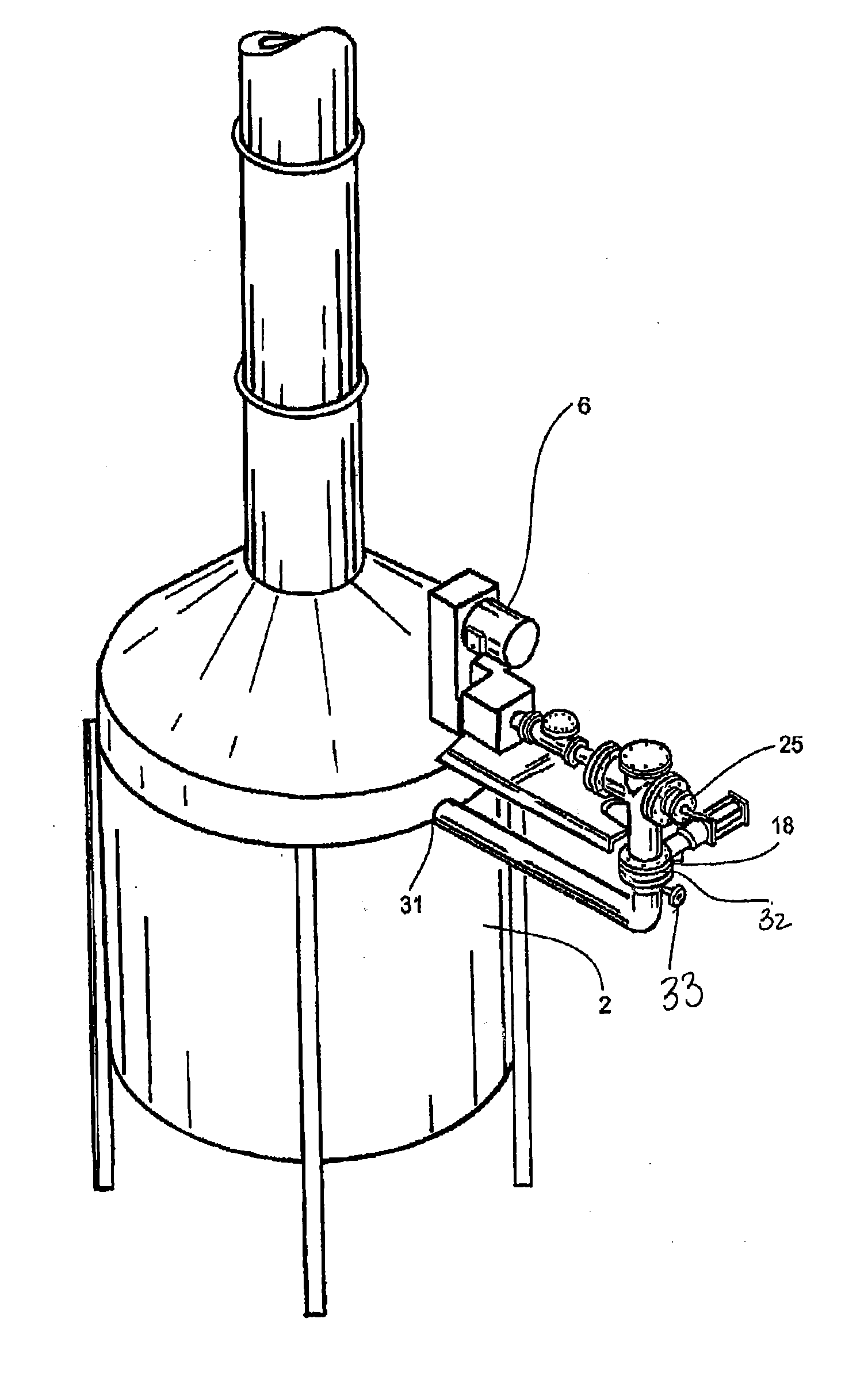
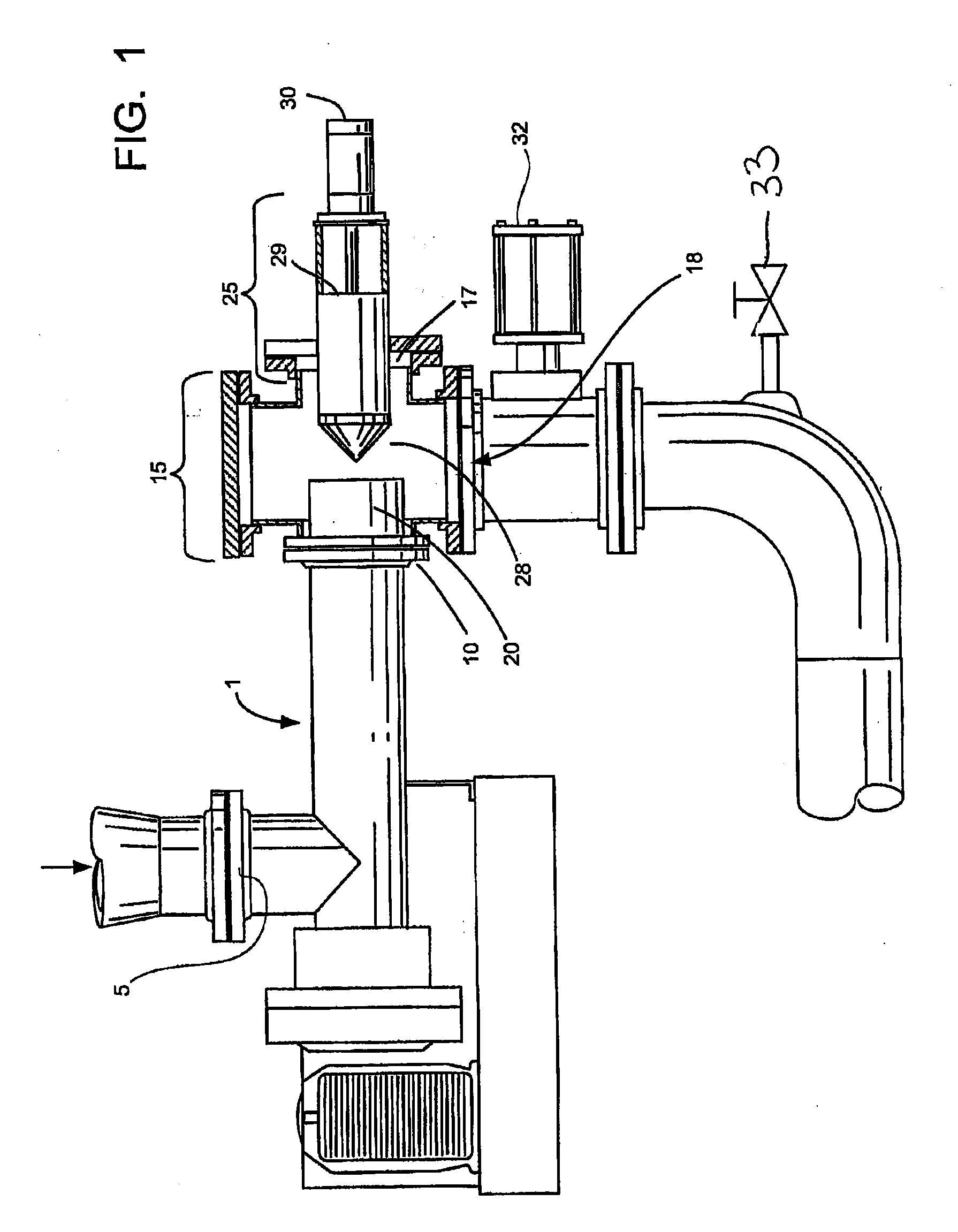
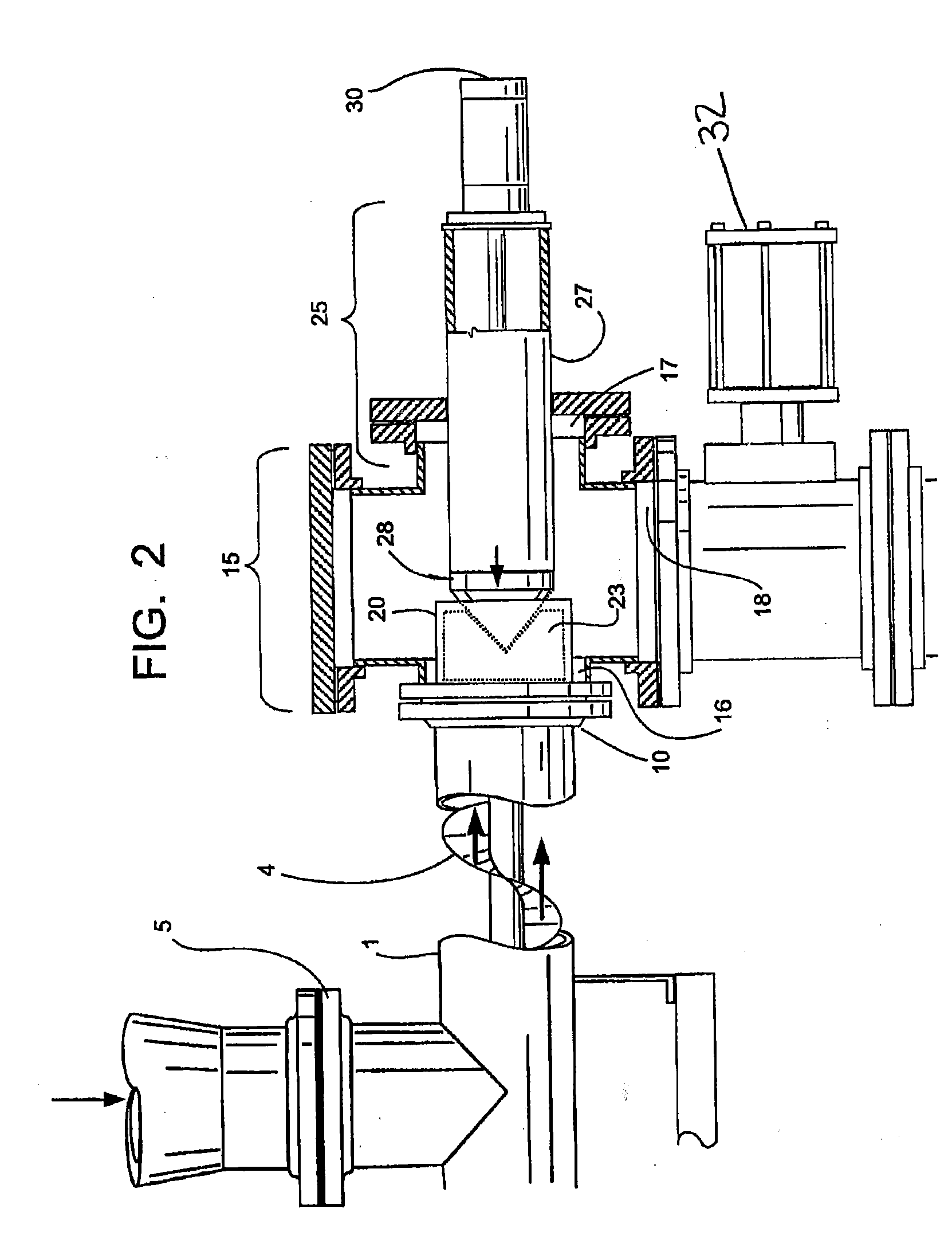
[0039]The following is an example of the apparatus of the present invention. The material retention chamber 20 has a three inch diameter, the angle of the vertex of the cone of the conical end 28 is approximately 45 degrees, the utilized motor horsepower is 10 hp, the maximum speed of the auger is 50 rpm, and the auger diameter is 3 inches. The sawdust wood rate of feed is about 100 pounds per hour and the reactor pressure is 10 psig, the sawdust has an average moisture of about 10% and grain top size of about ⅛ inch.

example 2

[0040]The following is an example of a second embodiment of apparatus of the present invention. The material is sawdust and the material retention chamber 20 has an eight inch diameter, the angle of the vertex of the cone of the conical end 28 is between 70 and 80 degrees. The auger speed is 25 rpm, producing a feed rate of about 800 pounds of sawdust per hour with a reactor pressure of about 40 psig. The useful horsepower of the motor is 15 hp. The auger size is 8 inches in diameter. When the pressurized vessel 2 is run at 30 psig, the pressure on the rear end 29 is 60 psig. It is noted that the 50% increase of horsepower utilized in example 2 represents the ratio of frictional area over the volume for the diameter (3 vs. 8 inches) of the feeders. It is observed that for materials other than sawdust (at the given % of moisture) a starting point is proposed in the application of the data above as adjusted for the coefficient of friction between the “new” material and the material of...


PUM


Abstract

The present invention relates to an improved apparatus and method for conveying fibrous, solid and slurry materials, such as granulated wood, rice hulls, chopped cane and the like, to a pressurized vessel, wherein the material being conveyed is compacted in the feeder in a controlled manner to create a seal at the feeder exit into the pressurized vessel whereby the processing pressure in the vessel is maintained. The invention is particularly useful when used in conjunction with a biomass reactor for the production of gas selectively rich in hydrogen and carbon containing components, such as carbon monoxide, carbon dioxide and methane, which in turn, may be converted into a select end product fuel, such as methanol or ethanol or used as a feed gas for an industrial power plant, such a the biomass reactor for producing gas.

Description

CROSS-REFERENCE TO RELATED APPLICATIONS[0001]This application claims priority of Provisional Application for Patent, Ser. No. 60 / 951,198. filed Jul. 21, 2007, which application is incorporated herein by reference.STATEMENT REGARDING FEDERALLY SPONSORED RESEARCH OR DEVELOPMENT[0002]Funding from Department of Energy under grant DE-FG36-02GO12025 was received in conjunction with the development of this technology.REFERENCE TO A “MICROFICHE APPENDIX”[0003]Not applicableBACKGROUND OF THE INVENTION[0004]The present invention relates to an improved apparatus and method for conveying fibrous, solid and slurry materials, such as granulated wood, rice hulls, chopped cane and the like, to a pressurized vessel. The material being conveyed is compacted in the feeder in a controlled manner to create a seal at the feeder exit to the pressurized vessel which maintains the pressure in the vessel. The invention is particularly useful when used in conjunction with a biomass reactor for the production ...

Claims


Application Information

Patent Timeline
IPC IPC(8): C10J3/30
CPCC10L5/44Y02E50/10Y02E50/30C10J3/30C10J2200/09C10J2300/0973C10J2300/0916C10J2300/092C10J2300/0956C10J2300/0959C10J2200/15Y02P20/145
Inventor PEARSON, LARRY E.
Owner PEARSON LARRY E
Learn More