Variable Speed Hub

a variable speed, hub technology, applied in the direction of propellers, engine control parameters, water-acting propulsive elements, etc., can solve the problems of hub force, inability to optimally use the power of the wind, tendency to go too fast, etc., to achieve the effect of optimizing the blade speed

Inactive Publication Date: 2009-01-22
LM GLASSFIBER
View PDF13 Cites 16 Cited by
  • Summary
  • Abstract
  • Description
  • Claims
  • Application Information

AI Technical Summary

Benefits of technology

[0016]According to a further embodiment the system comprises one or more position meters for measuring the position of at least one blade, said position being used for controlling the angular displacement of at least one blade in the rotor plane. Hereby the advantageous aspect is accomplished that the speed of the wind can be adjusted in response to where in the rotation cycle the blade is currently located. This may contribute to optimising the speed of the blade while simultaneously th

Problems solved by technology

The rate of rotation of the blades being adjusted on the basis of wind speed at the hub, the blade will have a propensity to go too fast when it is situated in the upper half of its rotation cycle, and too slowly when it is situated in the bottom half of the rota

Method used


Image

  • Variable Speed Hub
  • Variable Speed Hub
  • Variable Speed Hub

Examples


Embodiment Construction

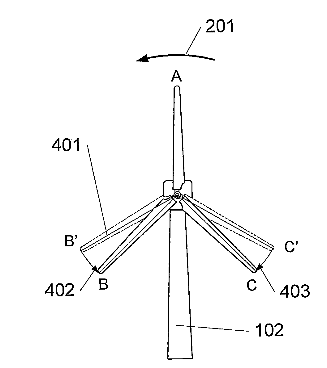
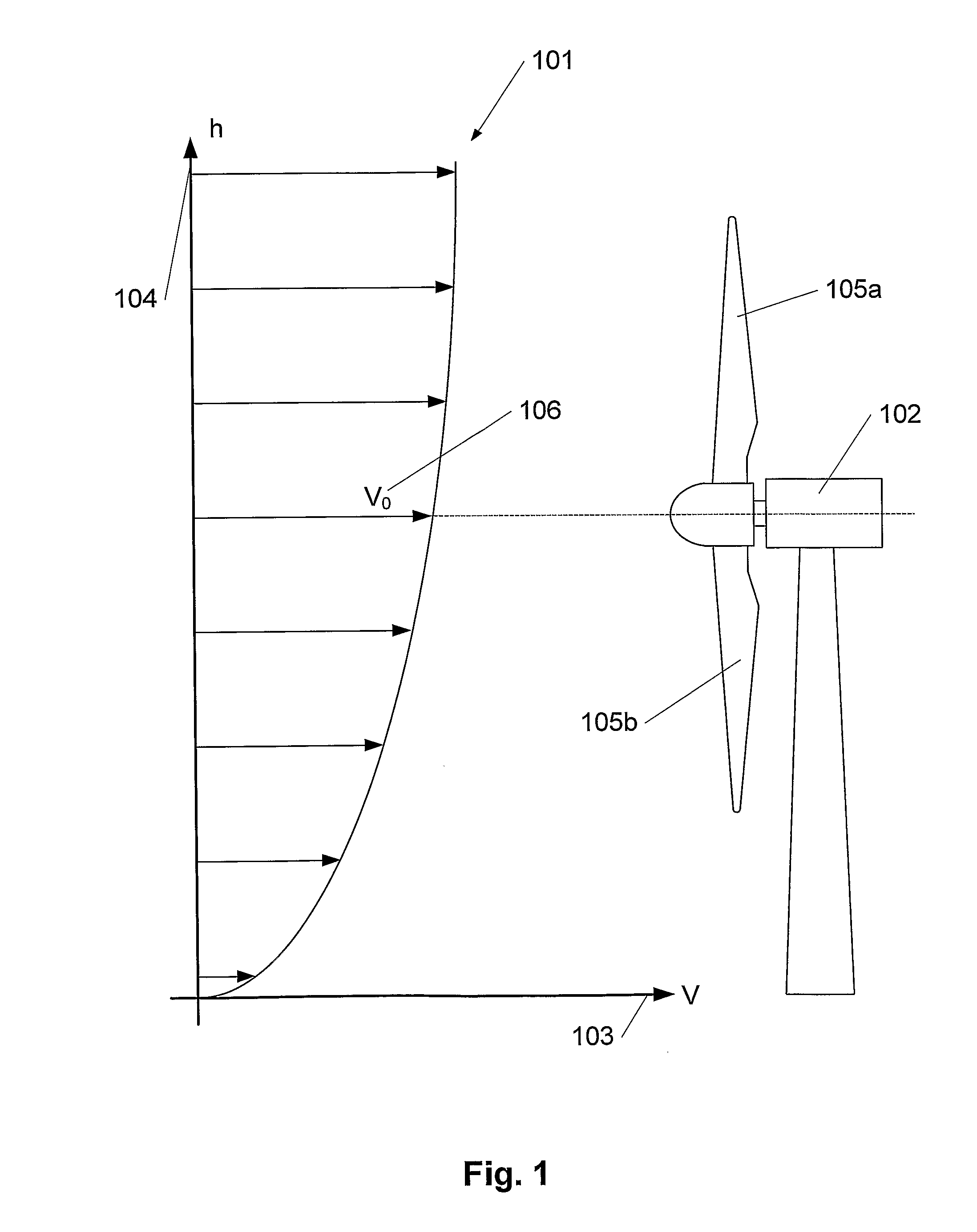
[0027]FIG. 1 illustrates a wind profile (101) in front of a wind turbine (102). The speed of the wind, V, is indicated on the horizontal axis (103), whereas the height, h, above ground level is indicated on the vertical axis (104). The shape of the wind profile depends on the terrain in which the profile is to describe the wind, but it applies in general that the speed of the wind is increased when the height increases. Therefore the individual blades of the wind turbine will be influenced by different wind speeds in response to where in the rotation cycle the blade (105a, 105b) is located. Thus, the uppermost blade (105a) experiences a higher speed of wind than the lowermost blade (105b). The speed of the wind at the same height as the hub of the wind turbine is designated V0 (106). In order to use as much power of the wind as possible, each individual blade tip speed is to be adjusted proportionally with the speed of the wind. Therefore, in this invention, the blades in the wind t...


PUM


Abstract

A method of adjusting the speed of blades rotating in a rotor plane on a wind turbine, wherein the angle between at least two blades in the rotor plane is changed, whereby the tip speed of each individual blade can be optimised relative to the current speed of the wind experienced by the blade. Hereby it is possible to take into consideration the variation of the wind as a function of the height above ground level, and the yield of the wind turbine can be increased. The angular displacement of each blade can be changed individually independently of the remainder of the blades and cyclically. The method also comprises that each blade is accelerated on its way upwards in the rotation cycle and decelerated on its way down. Further details are provided about a system for controlling blades in a wind turbine comprising one or more wind speed meters, position meters, and/or acceleration meters, based on which parameters control of the angular displacement of each blade in the rotor plane is performed.

Description

[0001]The invention relates to a method for speed adjustment of blades rotating in a rotor plane on a wind turbine and a wind turbine with adjustable blades.BACKGROUND[0002]In the context of wind turbines for power production, the number of revolutions of the blades is adjusted in accordance with the speed of the wind to the effect that as much wind power as possible is converted into electric power. To use to advantage as much as possible of the wind power, the blade tip speed describing the speed of the blade tip is to be adapted to the speed of the wind. This is accomplished by changing the rate of revolution of the blades in pace with the speed of the wind changing. When the wind power is exploited optimally, the speed of the blade tip is proportional to the speed of the wind, meaning that the blade tip speed is increased when the speed of the wind increases and is correspondingly lowered when the speed of the wind slows down.[0003]Today, the blades of a wind turbine are constru...

Claims


Application Information

Patent Timeline
IPC IPC(8): F03D7/04
CPCF03D7/02F03D7/0276Y02E10/723F05B2270/32F05B2270/101Y02E10/72
Inventor SORENSEN, TOMMY
Owner LM GLASSFIBER
Why Eureka
Try Eureka