Electrofusion fitting for a composite pipe

a technology of electrofusion and composite pipes, applied in the direction of hose connections, pipe elements, mechanical equipment, etc., can solve the problems of metal barrier layer, potential delamination problems, and certain complications

Inactive Publication Date: 2009-01-29
UPONOR INNOVATION AB
View PDF12 Cites 9 Cited by
  • Summary
  • Abstract
  • Description
  • Claims
  • Application Information

AI Technical Summary

Benefits of technology

[0032]The invention may find application in the electrofusion joining and connecting of a wide range of composite pipes. It is especially suitable for the connection of polyolefin composite pipes, and particularly polyethylene (PE and PE-X) composite pipes. Such pipes, when provided with aluminium or other metallic barrier layers normally require the presence of adhesive layers in order to bond the inner and outer p

Problems solved by technology

The use of a metallic barrier layer does, however, give rise to certain complications.
For example, non-polar polymeric materials such as polyethylene do not bond to aluminium, giving rise to potential delamination issues.
Thus, in manufacturing processes wherein the inner plastics layer is directly extruded into a freshly formed and welded aluminium tube comprising the barrier layer, the thermal shrinkage of the hot extruded inner plastics layer tends to cause delamination, requiring the use of a high strength adhesive between the inner plastics layer and the aluminium tube.
Atmospheric moisture, or fluid from the pipe, can track along the barrier layer surfaces or diffuse through the adhesive layers causing delamination and structural failure of the pipe.
This conventional coupler has, however, no means to protect the exposed barrier layers at the cut pipe ends

Method used


Image

  • Electrofusion fitting for a composite pipe
  • Electrofusion fitting for a composite pipe
  • Electrofusion fitting for a composite pipe

Examples


Embodiment Construction

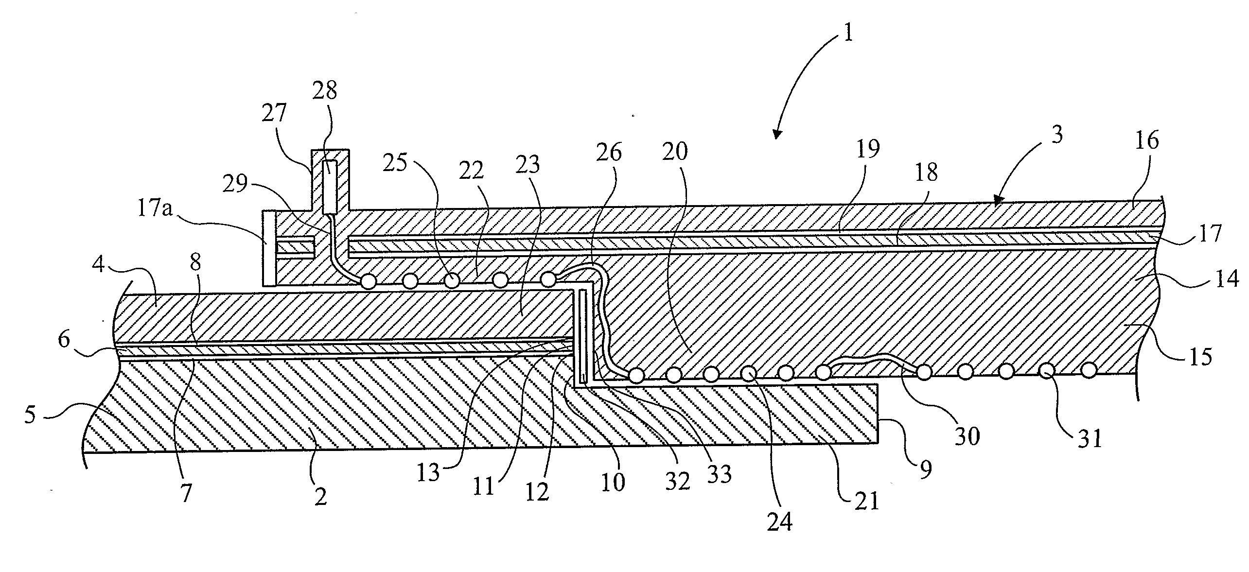
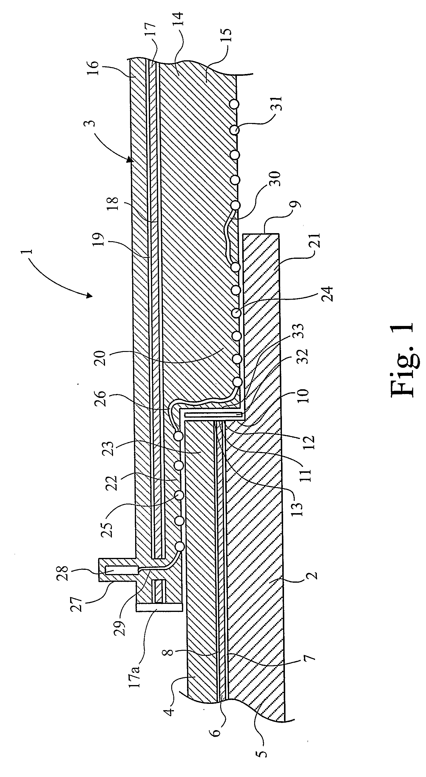
[0037]Referring firstly to FIG. 1, there is shown an electrofusion joint, illustrated generally at 1, comprising a composite pipe 2 and an electrofusion in-line coupler illustrated generally at 3. The composite pipe comprises an outer plastics layer 4, an inner plastics layer 5 and an aluminium barrier layer 6. The aluminium barrier layer 6 is bonded to the inner and outer plastics layers by adhesive layers 7 and 8 respectively. A portion of the cut end 9 of the pipe is cut back in order to provide a step or abutment 10, which includes the exposed edges 11, 12 and 13 of the aluminium barrier layer 6, and the adhesive layers 7 and 8 respectively.

[0038]The electrofusion coupler 3 comprises a body 14 comprising an inner fusible plastics layer 15, an outer plastics layer 16 and an aluminium barrier layer 17. The aluminium barrier layer is bonded to the inner and outer plastics layers of the body 14 by adhesive layers 18 and 19 respectively. The body 14 of the electrofusion coupler has a...


PUM

PropertyMeasurementUnit
Diameteraaaaaaaaaa
Electrical resistanceaaaaaaaaaa
Metallic bondaaaaaaaaaa

Abstract

An electrofusion fitting for a composite plastics pipe, the pipe comprising at least one inner plastics layer, at least one outer plastics layer and at least one barrier layer therebetween, the fitting comprising a tubular body formed at least in part from a thermoplastic polymer material and adapted to receive a cut end of the pipe, and a plurality of electric heating elements disposed within the body, the body having a first section adapted to receive a length of the inner plastics layer and a second section adapted to receive a cut-back length of the outer plastics layer, each of the first and second sections being provided with a discrete heating element adapted, when energized, to make a fusion joint between the section and its adjacent pipe layer, such that the exposed barrier layer at the cut end of the pipe is environmentally sealed on each side by a fusion joint.

Description

[0001]This invention relates to fittings for composite pipes, and more particularly to electrofusion fittings for composite plastic pipes having an internal barrier or strengthening layer.BACKGROUND[0002]Multilayer pipes, wherein at least one of the layers comprises a barrier or strengthening layer, are well known and a great many have been described in the literature. Multilayer pipes are used, for example, when improved long term strength at elevated temperatures is needed or, when barrier properties against fluid permeation or ingress of contaminants are required. Multilayer pipes can comprise dissimilar materials for particular applications. In particular, multilayer pipes having oxygen diffusion barrier layers have been proposed. The diffusion barrier can be a polymeric layer such as EVOH, or an impermeable metallic layer which provides both a diffusion barrier and a strengthening layer.[0003]In recent years multilayer pipes having aluminium or aluminium-based metallic barrier ...

Claims


Application Information

Patent Timeline
IPC IPC(8): F16L47/03B29C65/34B29C65/36B29C65/48
CPCB29C65/342B29C65/3424B29C65/3428B29C65/344B29C65/3468B29C65/36B29C65/362B29C65/3628B29C65/364B29C66/12821B29C66/1284B29C66/5221B29C66/5229B29C66/52292B29C66/52294B29C2793/0054B29C2793/0081B29K2023/00B29K2023/06B29K2023/0625B29K2023/0633B29K2023/0641B29K2023/065B29K2023/0691B29K2023/083B29K2023/086B29K2023/12B29K2023/18B29K2027/00B29K2027/06B29K2055/02B29K2069/00B29K2077/00B29K2096/005B29K2096/04B29K2101/12B29K2105/0085B29K2105/0088B29K2105/24B29K2305/02B29K2305/10B29K2305/12B29K2995/0067B29L2009/00B29L2009/003F16L47/03B29C65/348B29C65/3632B29C65/368B29C66/52295B29C66/91651B29C66/1222B29C66/1226B29C66/1282B29C66/1286B29C65/3432B29C66/3472B29C65/48B29C66/116B29C65/00B29C66/128B29C66/347B29C66/9161B29C66/50B29C66/72321B29C66/7392B29C66/73755B29C66/73921B29C66/7394B29C66/71B29C66/712B29K2023/10B29K2023/08
Inventor BOWMAN, JEREMY
Owner UPONOR INNOVATION AB
Why Eureka
Try Eureka