Fixed wavelength mid infrared laser source with an external cavity

a laser source and infrared technology, applied in semiconductor lasers, instruments, optical elements, etc., can solve the problems of low yield of process, inefficient and expensive process, etc., and achieve high production yield, large lasing wavelength adjustment, and very precise manufacturing process.

Inactive Publication Date: 2009-01-29
DAYLIGHT SOLUTIONS
View PDF28 Cites 23 Cited by
  • Summary
  • Abstract
  • Description
  • Claims
  • Application Information

AI Technical Summary

Benefits of technology

[0005]Embodiments of the present invention are directed towards a MIR laser source that produces a fixed frequency output beam that is within the MIR range. In one embodiment, the MIR laser source includes a QC gain media, and a wavelength dependent (“WD') reflector that is spaced apart from the QC gain media and that cooperates with the QC gain media to form an external cavity. By configuring a WD reflector to form an external cavity, control of the wavelength of the output beam may be gained. In this embodiment, the WD reflector is used to precisely tune a lasing wavelength of the external cavity, and the position of the WD reflector relativ

Problems solved by technology

Unfortunately, none of the methods used to grow the periodic grating on the QC gain media are completely precise.
Thus, the yield of this process is low and the process is in

Method used


Image

  • Fixed wavelength mid infrared laser source with an external cavity
  • Fixed wavelength mid infrared laser source with an external cavity
  • Fixed wavelength mid infrared laser source with an external cavity

Examples


Embodiment Construction

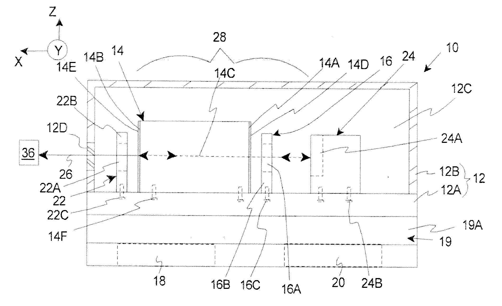
[0024]FIG. 1 illustrates a MIR laser source 10 according to an embodiment of the present invention that includes a source frame 12, a quantum cascade (“QC”) gain media 14, a cavity optical assembly 16, a power source 18 (illustrated in phantom), a temperature controller 19, a laser electronic controller 20 (illustrated in phantom), an output optical assembly 22, and a wavelength dependant (“WD”) feedback assembly 24 that cooperate to generate a fixed, output beam 26 that is in the MIR range. The design of each of these components can be varied pursuant to the teachings provided herein. In should be noted that the MIR laser source 10 can be designed with more or fewer components than described above.

[0025]As an overview, in certain embodiments, the WD feedback assembly 24 includes a wavelength dependent (“WD”) reflector 24A (illustrated in phantom) that cooperates with the QC gain media 14 to form an external cavity 28. Further, the WD reflector 24A can be tuned to adjust the lasing ...


PUM


Abstract

A MIR laser source that produces a fixed frequency output beam that is within the MIR range includes a QC gain media, and a wavelength dependent (“WD') feedback assembly that is spaced apart from the QC gain media and that cooperates with the QC gain media to form an external cavity. The WD feedback assembly may be used to precisely tune and control a lasing wavelength of the external cavity, and the position of the WD feedback assembly relative to the QC gain media may be fixed to maintain the precise lasing wavelength of the external cavity. With this design, each MIR laser source can be individually tuned to achieve the desired fixed frequency output beam that is within the MIR range.

Description

BACKGROUND OF THE INVENTION[0001]Mid Infrared (“MIR”) laser sources that produce a fixed wavelength beam can be used in many fields such as, in medical diagnostics, pollution monitoring, leak detection, analytical instruments, homeland security and industrial process control. For example, MIR laser sources can be used in the detection of certain molecules found in human breath that correlate to existing health problems such as asthma, kidney disorders and renal failure.[0002]One type of fixed wavelength, MIR laser source is commonly referred to as Distributed Feedback (“DFB”) and includes a quantum cascade (“QC”) gain media, and a periodic grating either on the surface of the QC gain media or close to the active region of the QC gain media. The periodic grating on the QC gain media preferentially favors certain laser modes. This results in a MIR laser source having a fixed wavelength beam.[0003]Commonly, the periodic grating is grown using the same methods used to grow the QC gain m...

Claims


Application Information

Patent Timeline
IPC IPC(8): H01S3/13
CPCB82Y20/00G02B5/1828H01S3/1055H01S5/02208H01S5/3401H01S5/02252H01S5/02415H01S5/02438H01S5/141H01S5/02248H01S5/02325H01S5/02326
Inventor ARNONE, DAVID F.DAY, TIMOTHY
Owner DAYLIGHT SOLUTIONS
Why Eureka
Try Eureka