Phase-digital converter having hierarchical structure

a time-to-digital converter and hierarchical structure technology, applied in the field of hierarchical time-to-digital converters, can solve the problems of deteriorating analog circuit performance, reducing power consumption, and unable to make a time-to-digital converter having a smaller resolution than the basic delay circuit render, so as to reduce the size of the circuit, wide phase detection range, and increase resolution

Inactive Publication Date: 2009-01-29
KOREA UNIV IND & ACADEMIC CALLABORATION FOUND
View PDF4 Cites 20 Cited by
  • Summary
  • Abstract
  • Description
  • Claims
  • Application Information

AI Technical Summary

Benefits of technology

[0010]The present invention is directed to a new time to digital converter that increases a resolution and compensates for a phase difference by stages using a hierarchical structure to drastically reduce a size of a circuit while simultaneously satisfying a wide phase detection range and a high resolution, and thus has a phase detection range varies according to the resolution.

Problems solved by technology

In addition, reduction in supplied voltage level is resulting in decrease in power consumption.
However, the reduction in circuit line width causes an increase in leakage current and results in deterioration in performance of analog circuits.
However, the time to digital converter cannot detect a phase difference within the specific delay T. The delay T of the time to digital converter is referred to as a resolution of the time to digital converter, which is determined by a phase difference caused by basic delay circuits of the delay stages.
In general, a basic delay circuit is made of two inverters having the minimum delay, and it is impossible to make a time to digital converter having a smaller resolution than that of the basic delay circuit renders.
However, when the resolution of the conventional time to digital converter increases, a phase detection range is reduced.

Method used


Image

  • Phase-digital converter having hierarchical structure
  • Phase-digital converter having hierarchical structure
  • Phase-digital converter having hierarchical structure

Examples


Embodiment Construction

[0022]Hereinafter, exemplary embodiments of the present invention will be described in detail. The present invention is not limited to the exemplary embodiments disclosed below, but rather can be implemented in various forms. The following exemplary embodiments are described in order to fully enable those of ordinary skill in the art to embody and practice the present invention.

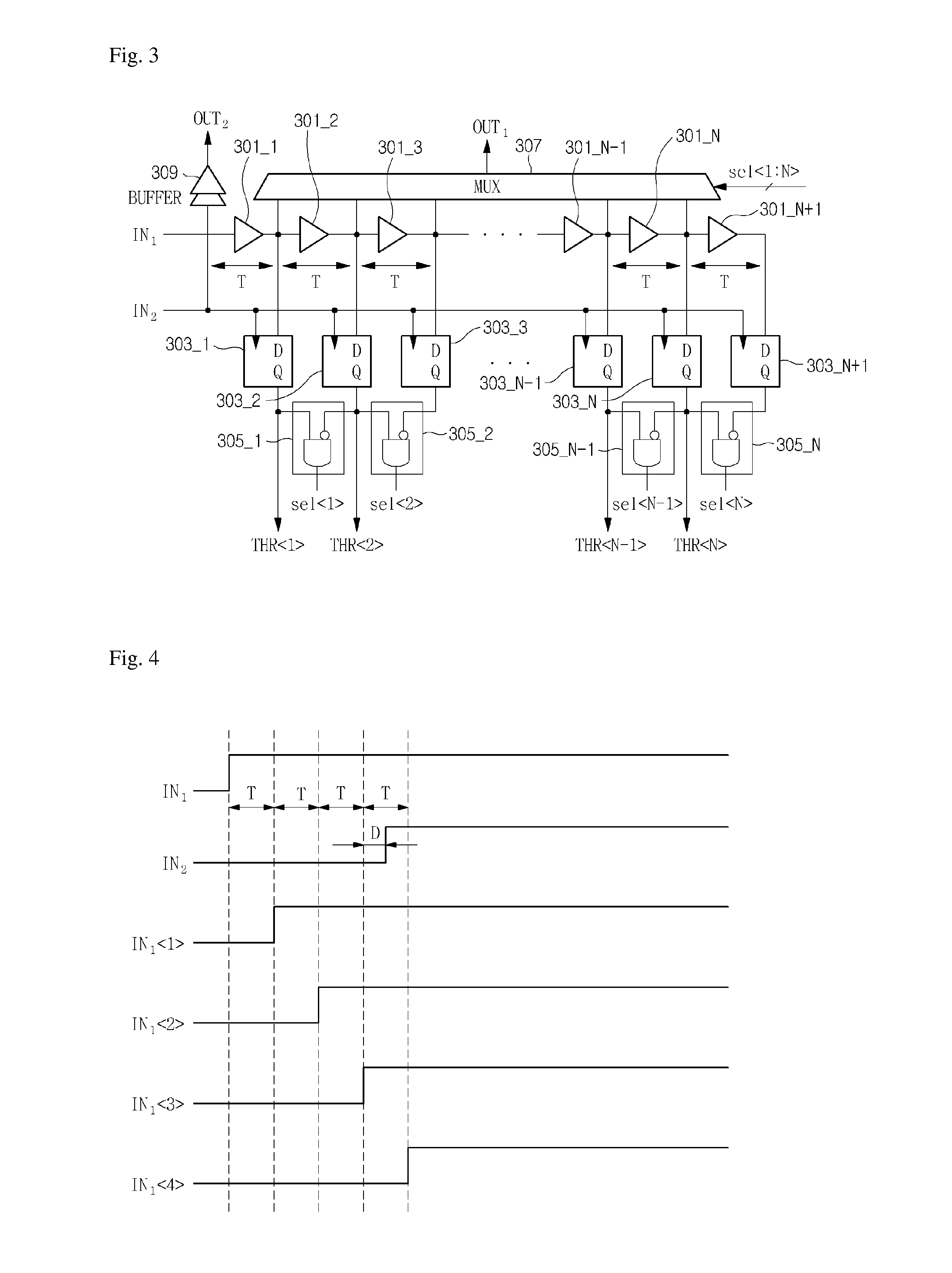
[0023]FIG. 3 is a circuit diagram of a time to digital converter according to an exemplary embodiment of the present invention, and FIG. 4 is a timing diagram illustrating operation of the time to digital converter according to an exemplary embodiment of the present invention.

[0024]Referring to FIGS. 3 and 4, the time to digital converter according to an exemplary embodiment of the present invention includes delay stages 301_1, 301_2, 301_3, . . . , 301_N−1, 301_N and 301_N+1, flip-flops 303_1, 303_2, 303_3, 303_N−1, 303_N and 303_N+1, selection signal generators 305_1, 305_2, . . . , 305_N−1 and 305_N, a Mul...


PUM


Abstract

A time to digital converter having a hierarchical structure is provided. The time to digital converter includes: a plurality of delay stages for sequentially delaying a first signal for a specific delay time; a plurality of flip-flops for comparing delay signals of the first signal delayed by the delay stages with a second signal, and generating different outputs before and after a phase difference between the delay signals of the first signal and the second signal becomes smaller than a resolution of the phase detector; a selection signal generator for generating a selection signal for selecting a signal most similar to the second signal among the delay signals of the first signal from the outputs of the flip-flops; and a Multiplexer (MUX) for receiving the delay signals of the first signal and the selection signal, and outputting the signal most similar to the second signal among the delay signals of the first signal.

Description

CROSS-REFERENCE TO RELATED APPLICATION[0001]This application claims the benefit of Korean Patent Application No. 2007-0073967, filed Jul. 24, 2007, the disclosure of which is hereby incorporated herein by reference in its entirety.BACKGROUND OF THE INVENTION[0002]1. Field of the Invention[0003]The present invention relates to a hierarchical time to digital converter, and more particularly, to a hierarchical time to digital converter in which a resolution is increased by stages while a phase is compensated for to implement a high resolution and a wide phase detection range.[0004]2. Description of the Related Art[0005]With development of semiconductor manufacturing process technology, circuit line widths have been reduced, and thus the degree of circuit integration is increasing. In addition, reduction in supplied voltage level is resulting in decrease in power consumption. However, the reduction in circuit line width causes an increase in leakage current and results in deterioration ...

Claims


Application Information

Patent Timeline
Patent Type & Authority Applications(United States)
IPC IPC(8): H03D1/00H04L27/06
CPCG04F10/06H03K2005/00286H03K5/159H03M1/82
Inventor KIM, CHULWOOSONG, MINYOUNGAHN, SUNGHOON
Owner KOREA UNIV IND & ACADEMIC CALLABORATION FOUND
Why Eureka
Try Eureka