Method and apparatus for anchoring cardiovascular implants

a cardiovascular implant and anchoring technology, applied in the field of medical devices, can solve the problems of ineffective anchoring mechanism at the time of anchored device placement, and achieve the effects of reducing the overall footprint of the implanted device, reducing the risk of migration, and reducing the invasiveness of insertion

a cardiovascular implant and anchoring technology, applied in the field of medical devices, can solve the problems of ineffective anchoring mechanism at the time of anchored device placement, and achieve the effects of reducing the overall footprint of the implanted device, reducing the risk of migration, and reducing the invasiveness of insertion

US20090030435A1Inactive Publication Date: 2009-01-29THERANOVA LLC

Image

  • Method and apparatus for anchoring cardiovascular implants
  • Method and apparatus for anchoring cardiovascular implants
  • Method and apparatus for anchoring cardiovascular implants

Examples


Embodiment Construction

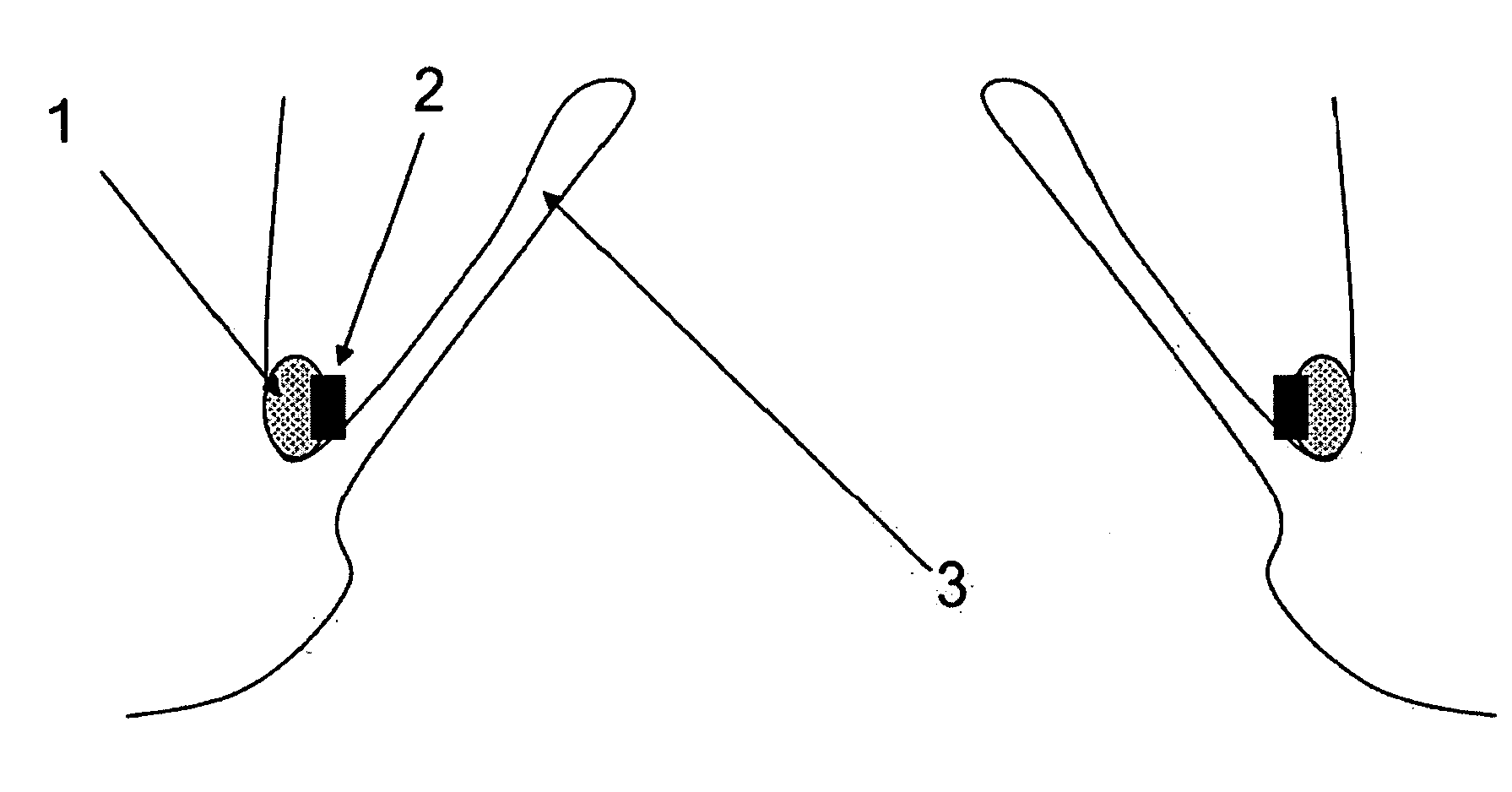
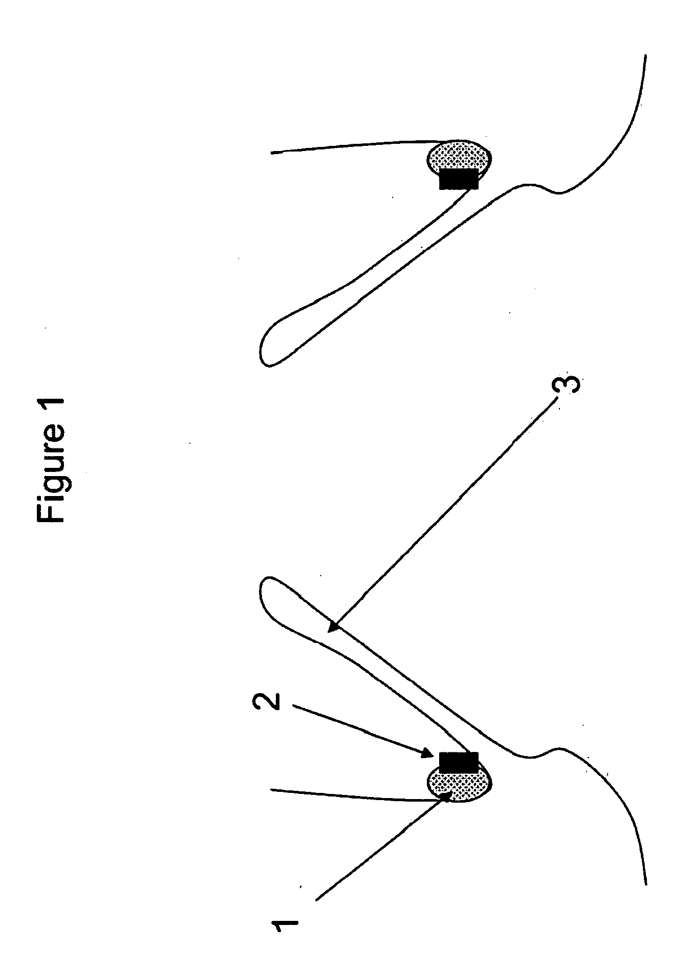
[0037]FIG. 1—This illustration represents the deployed anchoring element placed in the aortic valve region. As can be seen from the illustration, the anchoring element comprises a material to promote fibrotic ingrowth 1 and the attachment ring 2 designed to engage the aortic valve device. In this case, the device is deployed above the native aortic valve 3.

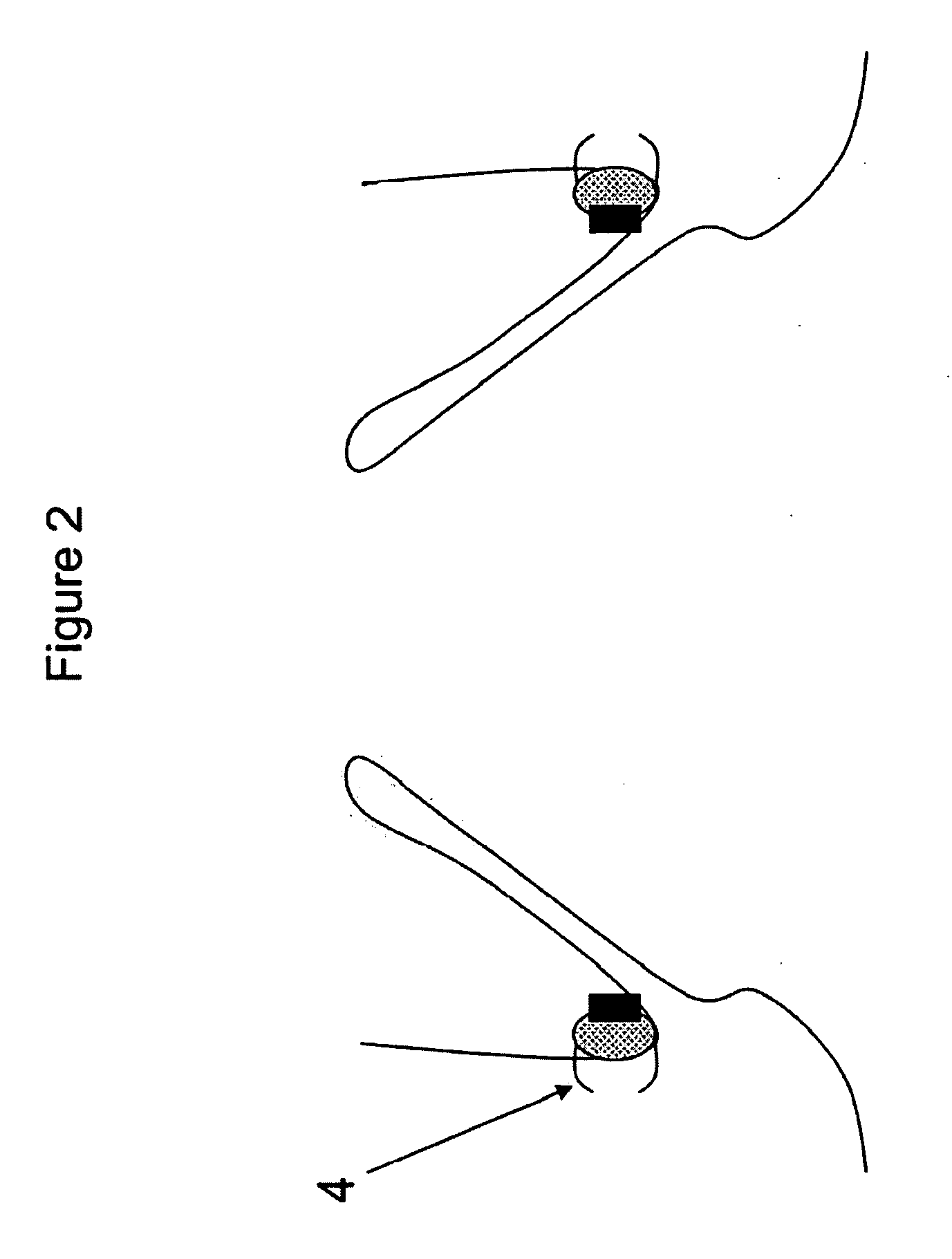
[0038]FIG. 2—This illustration represents the deployed anchoring element again placed in the aortic valve region but this time with clips to secure the anchoring element to the aorta. As can be seen from the illustration, the anchoring element comprises a material to promote fibrotic ingrowth 1, the attachment ring 2 designed to engage the aortic valve device and clips, staples, etc 4 for the attachment of the anchoring element to the aortic tissues. In this case, the device is deployed above the native aortic valve.

[0039]FIG. 3—This illustration represents the deployed anchoring element again placed in the aortic valve region but...


PUM


Abstract

Methods, devices and systems facilitate retention of a variety of therapeutic devices. Devices generally include an anchoring element, which has been designed to promote fibrotic ingrowth, and an anchored device, which has been designed to firmly engage the complementary region of the anchoring element. The anchoring element may be placed in a minimally invasive procedure temporally separated from the deployment of the anchored device. Once enough time has passed to ensure appropriate fixation of the anchoring element by tissue and cellular ingrowth at the site of placement, the anchored device may then be deployed during which it firmly engages the complementary region of the anchoring element. In this manner, a firm attachment to the implantation site may be made with a minimum of required hardware. Some embodiments are delivered through a delivery tube or catheter and while some embodiments may require laparoscopy or open surgery for one or more of the placement procedures. Some embodiments anchor devices within the cardiovascular tree while others may anchor devices within the gastrointestinal, peritoneal, pleural, pulmonary, urogynecologic, nasopharyngeal or dermatologic regions of the body. An alternative embodiment provides for the placement of the anchoring element and anchored device simultaneously, but allows for their removal separately. This embodiment allows the device, which may be placed only temporarily and be designed to be removed, to experience significant fibrotic ingrowth, but then to be easily detached from the ingrowth-anchored region to allow for simple and quick device removal.

Description

CROSS-REFERENCE TO RELATED APPLICATIONS[0001]This application claims the benefit of priority to U.S. Prov. Pat. App. 60 / 964,822 filed Aug. 15, 2007 and is a continuation-in-part of U.S. patent application Ser. No. 11 / 234,802 filed Sep. 26, 2005 which claims the benefit of priority to U.S. Prov. Pat. App. 60 / 613,205 filed Sep. 27, 2004, each of which is incorporated herein by reference in its entirety.FIELD OF THE INVENTION[0002]The present invention relates to the field of medical devices, in particular therapeutic vascular intervention devices requiring anchoring.BACKGROUND OF THE INVENTION[0003]In the last few decades, therapeutic intervention in the cardiovascular arena has seen major advances in the reducing the invasiveness of life-saving procedures. In fact, coronary artery bypass has been surpassed, now, by coronary stenting in most patients with two or fewer lesions. Continuing this trend, several cardiovascular stents and valves have been designed to facilitate minimally in...

Claims


Application Information

Patent Timeline
29 Jan 2009
Publication
US20090030435A1
IPC
A61B17/00; A61B17/08; A61F2/04; A61F2/24; A61F2/06
CPC
A61B17/00491; A61B17/04; A61B17/064; A61B17/08; A61F2/07; A61F2220/0091; A61F2/848; A61F2002/065
Inventors
BURNETT, DANIEL ROGERS; MANGRUM, SHANE