Disposal method and equipment for exhaust gas from combustion system

a technology of exhaust gas and combustion system, which is applied in the direction of indirect carbon-dioxide mitigation, heat recovery, energy input, etc., can solve the problems of low efficiency and inpractical use, and achieve the effects of easy and reliable discharge, excellent effects and advantages, and simplified apparatus construction

Inactive Publication Date: 2009-02-05
ELECTRIC POWER DEVELOPMENT COMPANY +1
View PDF17 Cites 32 Cited by
  • Summary
  • Abstract
  • Description
  • Claims
  • Application Information

AI Technical Summary

Benefits of technology

[0027]A method and an apparatus for disposing exhaust gas in a combustion equipment according to the invention can exhibit excellent effects and advantages. Liquefied carbon dioxide can be effectively taken out from combustion exhaust gas due to oxygen combustion. With the simply constructed apparatus, the other exhaust gas components condensed in the separation of the liquefied carbon dioxide from the combustion exhaust gas can be easily and reliably discharged to the

Problems solved by technology

However, any of them has lower efficiency and is not in practical use.
However, oxygen combustion involves a technical problem of hig

Method used


Image

  • Disposal method and equipment for exhaust gas from combustion system
  • Disposal method and equipment for exhaust gas from combustion system
  • Disposal method and equipment for exhaust gas from combustion system

Examples


Embodiment Construction

[0056]Next, embodiments of the invention will be described in conjunction with the attached drawings.

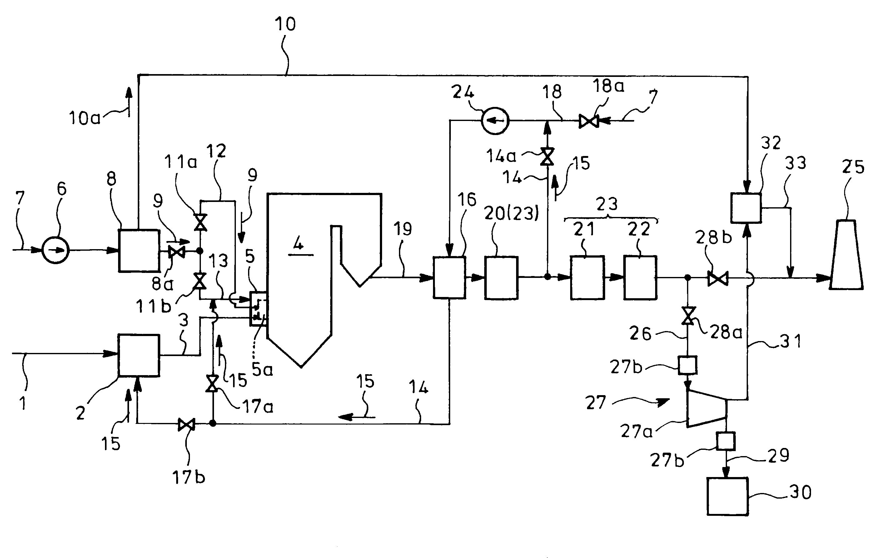
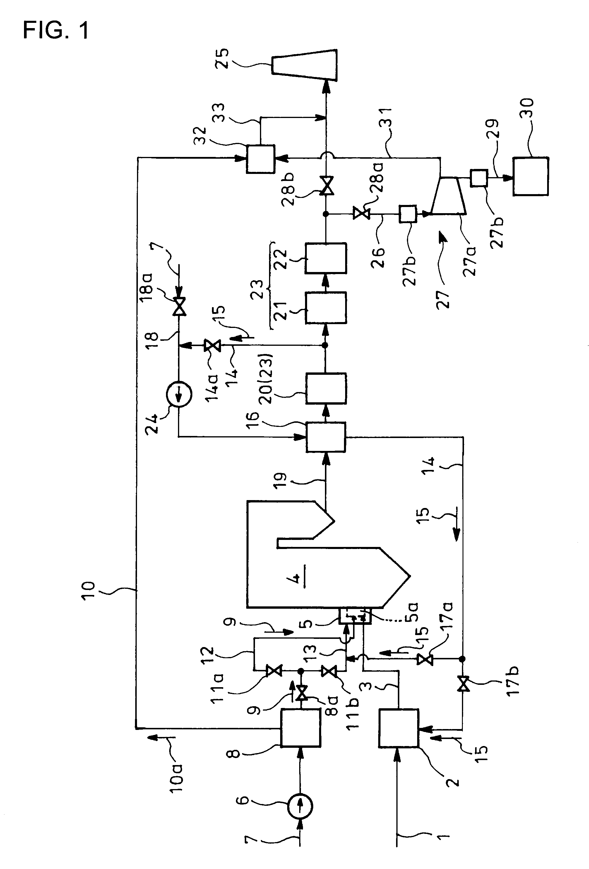
[0057]FIG. 1 is a block diagram showing an embodiment of an apparatus for carrying out the invention in which coal 1 as fuel is pulverized in a mill 2 as fuel supply means into pulverized coal 3 which is supplied to a burner 5a in a wind box 5 on a combustion furnace (boiler) 4. Air 7 from a blower 6 is supplied to an air separation unit 8 for separation of the air into oxygen 9 and other nitrogen-prevailing gas 10a, the resultant oxygen 9 being passed through a controller 8a and separated into direct and mixed supply lines 12 and 13 through oxygen flow rate controllers 11a and 11b, respectively, part of the oxygen 9 being directly supplied to the burner 5a, using the direct supply line 12. The remainder of the oxygen 9 is mixed in the mixed supply line 13 with part of recirculation gas 15 preheated in and guided from an air preheater 16, which will be detailed later, via recirculati...


PUM


Abstract

Carbon dioxide in combustion exhaust gas can be effectively separated and the combustion exhaust gas including the other exhaust gas components condensed through the separation of carbon dioxide can be discharged to the atmosphere.
Air 7 is separated by an air separation unit 8 into oxygen 9 and other nitrogen-prevailing gas 10a. The obtained oxygen 9 and coal 1 are burned by a burner 5a of a combustion furnace 4. Exhaust gas treatment is conducted for the resultant combustion exhaust gas from the furnace 4. Then, part of the combustion exhaust gas is recirculated to the burner 5a and the remaining unrecirculated combustion exhaust gas is compressed to take out liquefied carbon dioxide 29. The other exhaust gas components 31 unliquefied through the compression is mixed and diluted with the other nitrogen-prevailing gas 10a in the separation of the oxygen 9 from the air 7 in the air separation unit 8 and is discharged to the atmosphere.

Description

TECHNICAL FIELD[0001]The present invention relates to a method and an apparatus for disposing exhaust gas in a combustion equipment, and especially relates to a method and an apparatus for disposing exhaust gas in a combustion equipment which can effectively separate carbon dioxide from combustion exhaust gas to discharge the combustion exhaust gas having other exhaust gas components condensed through the separation of the carbon dioxide to the atmosphere.BACKGROUND ART[0002]Recently, global warming has been played up as environment-related issue on a mass global scale. It has been revealed that increase in concentration of carbon dioxide (CO2) in the atmosphere is one of main causes of the global warming, and thermal power plants are attracting attention as fixed sources of discharging the matter. Used as fuel for thermal power generation is petroleum, natural gas or coal. Especially coal, which has great mineable reserves, is expected to have increasing demand in the future.[0003]...

Claims


Application Information

Patent Timeline
IPC IPC(8): F23J15/00F25J3/00F23C9/08F23L7/00B01D53/62
CPCB01D53/62Y02E20/363C01B31/20F23C9/00F23D1/00F23G2900/00001F23J15/006F23J15/02F23J15/06F23J2215/50F23J2900/15061F23L7/007F25J3/04533F25J3/04563F25J2245/42F25J2260/42F25J2260/80Y02C10/04Y02E20/322Y02E20/344B01D2257/504F23L2900/07001Y02P20/129C01B32/50Y02C20/40Y02E20/32Y02E20/34Y02P20/151F23J15/00F23C99/00F23L7/00
Inventor OOKAWA, MASAFUMIFUJIMORI, TOSHIROTAKANO, SHINICHIYAMADA, TOSHIHIKO
Owner ELECTRIC POWER DEVELOPMENT COMPANY
Why Eureka
Try Eureka