Vacuum Evaporation Method for Forming a Multilayer Film Filter on a Plastic Component and Multi-Layer Film Filter Optical Image-Capturing Assembly with the Plastic Component

a technology plastic optical component, which is applied in the field of vacuum evaporation method for forming multi-layer film filter on plastic optical component and multi-layer film filter optical image capture assembly with the plastic component, can solve the problems of image distortion, increase of total optical path length, and consequential increase of material cost of multi-layer film filter optical image capture assembly, so as to reduce heat received, reduce heating effect, increase the distance between the evaporation sour

Inactive Publication Date: 2009-02-05
LARGAN PRECISION
View PDF3 Cites 9 Cited by
  • Summary
  • Abstract
  • Description
  • Claims
  • Application Information

AI Technical Summary

Benefits of technology

[0013]The multi-layer filter film is directly evaporated on one of the plastic optical components of the optical image-capturing assembly to replace the multi-layer film filter which uses the glass as the substrate. The optical image-capturing assembly of the present invention is unnecessary to be equipped with multi-layer film filter additionally, thus not only saving the raw material and the assembly cost of the optical image-capturing assembly, but also effectively reducing the volume of the optical image-capturing assembly.
[0014]The primary objective of the present invention is to provide a vacuum evaporation method for forming a multi-layer film filter on a plastic optical component and a multi-layer film filter optical image-capturing assembly with the plastic optical component. On the plastic optical component is directly deposited multi-layer filter film by vacuum evaporation method to replace the multi-layer film filter, so that the volume of the optical image-capturing assembly is reduced.
[0015]In order to achieve the abovementioned objective, on the plastic optical component is directly formed multiple layers of filter films including the films with high refractive index and the films with low refractive index by the vacuum evaporation method. According to the requirements, the multi-layer filter film can be applied onto any predetermined plastic optical component, so as to effectively reducing the volume of the optical image-capturing assembly.
[0017]As known from the conventional optical image-capturing assembly, high temperature severely affects the plastic optical component. In order to prevent the plastic optical component from being affected by the high temperature, the present invention restricts the vacuum evaporation time of each film not more than 4 minutes to reduce the heating effect from evaporation source to the plastic optical component. Increasing the distance between the evaporation source and the plastic optical component can reduce the heat received by the plastic optical component. Thereby, the present invention restricts the distance between the evaporation source and the plastic optical component more than 100 centimeters to avoid excessive heat transmitted to the plastic optical component from the evaporation source.
[0018]However, even though the abovementioned protect measures are used to prevent the plastic optical component from being affected by the evaporation source, there is still part of the heat of the evaporation source to be transmitted to the plastic optical component. Thereby, the present invention restrict that, each layer of film should stand for one to four minutes after being evaporated, so as to make the plastic optical component release the heat received form the evaporation through heat radiation. It is to be noted that, as long as the absolute temperature of the object is greater than 0, the object has the heat radiation effect, namely, the vacuum evaporation apparatus is also a heat radiation source which cannot be neglected. The greater the heat radiation difference between the plastic optical component and the vacuum evaporation apparatus is, the better the radiation cooling effect is. Hence, during the evaporation operation, the cooling water whose temperature is lower than 25° C. is used to cool the vacuum evaporation apparatus, so as to reducing the radiation heat released by the vacuum evaporation apparatus, thus facilitating accelerating the radiation cooling effect of the plastic optical component.

Problems solved by technology

If the multi-layer film filter 12 is not used, the photo will present the visible light image and the infrared image, thus causing the image distortion.
However, based on the Snell's law, the glass substrate of the multi-layer film filter will cause the increase of the total optical path length.
In addition, considering the cost, the use of the multi-layer film filter consequentially increases the material cost of the optical image-capturing assembly.
However, because the operation temperature of the evaporation source easily exceeds 2500° C., and the layer quantity of the multi-layer optical filter film is often more than 40, the temperature of the substrate exposed in the high temperature environment for a long time is to be between 250° C. and 350° C. Such a high temperature is helpful to form the tight film structure, but it cannot be applied to the plastic substrate whose softening temperature is from 80° C. to 150° C.

Method used


Image

  • Vacuum Evaporation Method for Forming a Multilayer Film Filter on a Plastic Component and Multi-Layer Film Filter Optical Image-Capturing Assembly with the Plastic Component
  • Vacuum Evaporation Method for Forming a Multilayer Film Filter on a Plastic Component and Multi-Layer Film Filter Optical Image-Capturing Assembly with the Plastic Component
  • Vacuum Evaporation Method for Forming a Multilayer Film Filter on a Plastic Component and Multi-Layer Film Filter Optical Image-Capturing Assembly with the Plastic Component

Examples


Embodiment Construction

[0027]The present invention will be clearer from the following description when viewed together with the accompanying drawings, which show, for purpose of illustrations only, the preferred embodiment in accordance with the present invention.

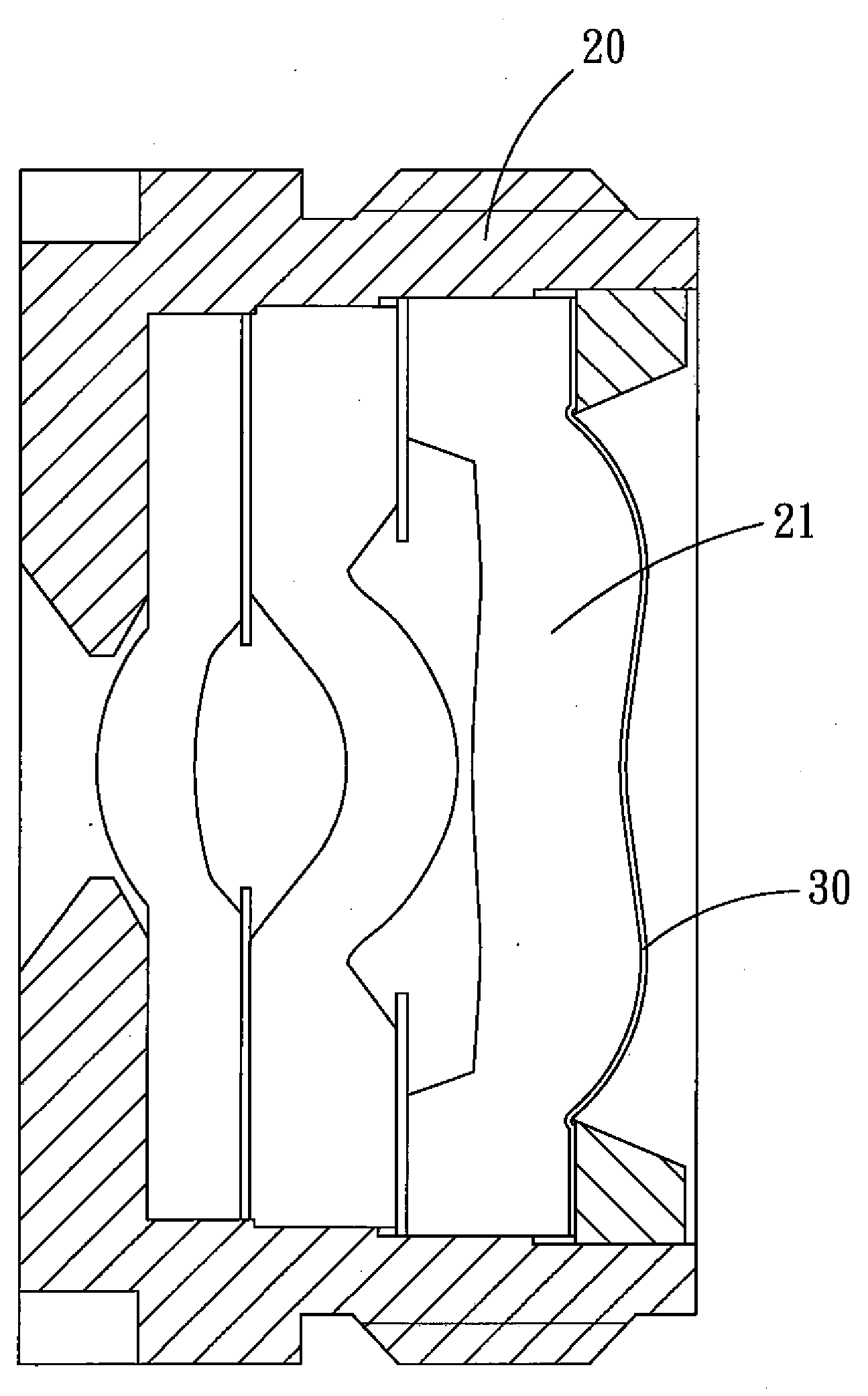
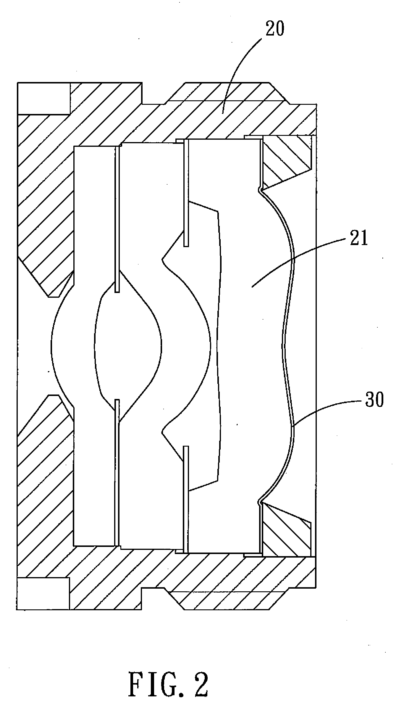
[0028]Referring to FIG. 2, this embodiment is a substitute for an IR cut filter The drawings illustrate a vacuum evaporation method for forming a multi-layer film filter on a plastic optical component and an optical image-capturing assembly with the plastic optical component made by the method in accordance with the present invention.

[0029]The vacuum evaporation method for forming a multi-layer film filter on a plastic optical component is to apply the multiple layers of filter films (IR cut film 30) onto a surface of a predetermined plastic optical component 21. The evaporation time of each layer of film is not more than four minutes. The distance between the evaporation source and the plastic optical component 21 is more than 100 centimeters. E...


PUM

PropertyMeasurementUnit
distanceaaaaaaaaaa
temperatureaaaaaaaaaa

Abstract

A vacuum evaporation method for forming a multi-layer film filter on a plastic optical component and a multi-layer film filter optical image-capturing assembly with the plastic optical component, in which the multi-layer film filter generally refers to various filters produced by adopting the optical interference principle. During the evaporation operation, the evaporation time of each film is not more than four minutes, the distance between the evaporation source and the plastic optical assembly must be more than 100 centimeters, and the ion assisted deposition is performed when the high refraction film and low refraction film are alternately laminated one upon the other to form more than 40 layers of films. The optical image capture assembly with the plastic optical component can be used without additionally adopting a multilayer film filter, thus effectively reducing the volume and the cost.

Description

BACKGROUND OF THE INVENTION[0001]1. Field of the Invention[0002]The present invention relates to a vacuum evaporation method for forming a multi-layer film filter on a plastic optical component and a multi-layer film filter optical image-capturing assembly with the plastic component, and more particularly to replacing the filters of various miniaturized plastic optical image-capturing assemblies.[0003]2. Description of the Prior Art[0004]With the miniaturization and precisation of the consumer electronic products, such as the digital camera, mobile phone, personal digital assistant (PDA), CD-ROM, multi-function video camera, or even the TV game etc, the optical image-capturing assembly will be required with higher performance. Therefore, the future designed and developed optical image capturing assembly must meet the requirements of both the miniaturization and the high resolution.[0005]Referring to FIG. 1 which shows the optical image-capturing assembly used in most of the mobile p...

Claims


Application Information

Patent Timeline
Patent Type & Authority Applications(United States)
IPC IPC(8): G02B1/10B05D5/06C23C14/00
CPCB29D11/00634G02B1/10B29D11/00865
Inventor CHU, KUO-CHIANGCHANG, CHIEN-PANG
Owner LARGAN PRECISION
Why Eureka
Try Eureka