
Portable medical monitoring and diagnostic system

a diagnostic system and medical monitoring technology, applied in the field of portable medical monitoring and diagnostic systems, can solve the problems of insufficient processing, unsatisfactory, and insufficient amount of processing, and achieve the effect of facilitating the work of patient care sta

Inactive Publication Date: 2009-02-05
NATIONAL UNIVERSITY OF IRELAND
View PDF34 Cites 46 Cited by
  • Summary
  • Abstract
  • Description
  • Claims
  • Application Information

AI Technical Summary

Benefits of technology

[0018]There are certain major advantages according to the present invention in that more efficient bed management and more efficient patient care may be achieved. For example, with the present invention it will be considerably easier for departments within the hospital to share beds without the control of the patient transferring from one department to another. It will also be easier for example if the first department or ward in a hospital transfers some of its patients to another ward for that first ward which is ultimately responsible for the patient, to track and monitor the patient's condition. It will greatly facilitate the work flow effectiveness in the hospital and will also allow this flexibility of movement and mobility of patients because the monitoring of the patient's condition will not be affected by the fact that internal roaming is occurring within the hospital. Also when for example a patient has moved from one department in the hospital to another department the original department with that patient's care responsibility residing in them will be able to locate the patient and in the event of an emergency will be able to quickly have the requisite medical attention for that patient.
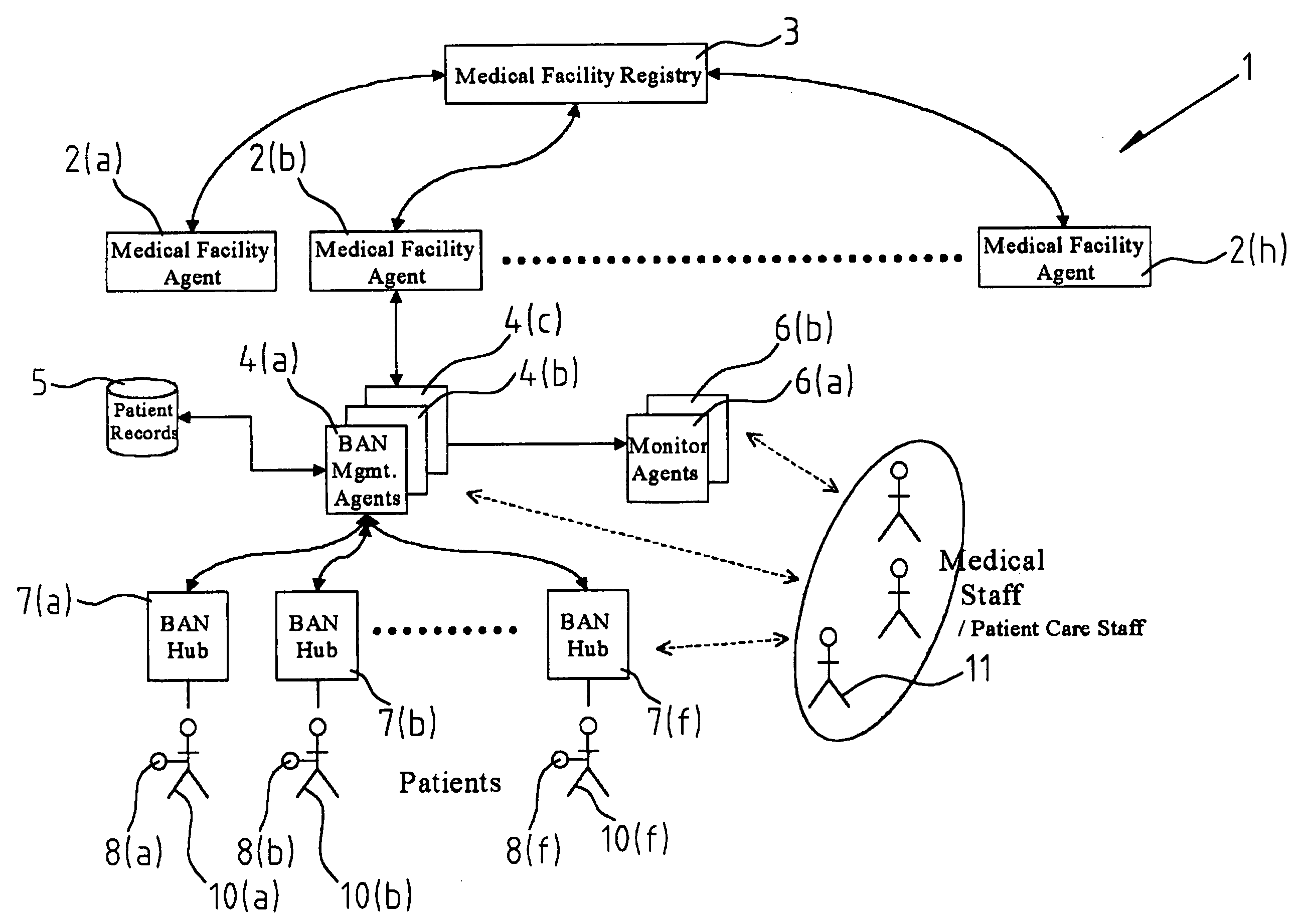
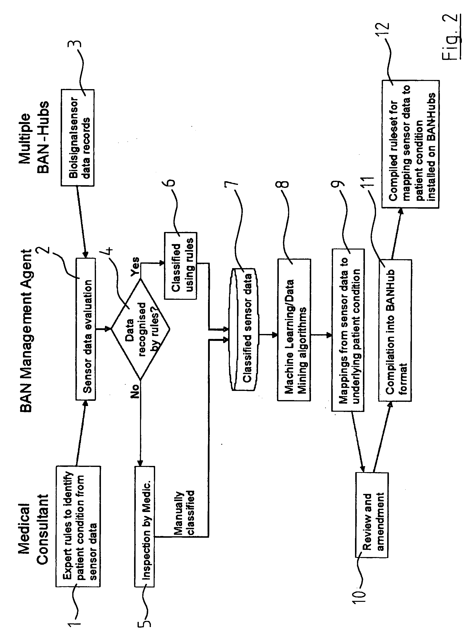
[0059]In another system according to the invention each BAN management agent comprises processing means for the reception and processing of patient diagnostic data from the BAN hub agents; data from the monitor agents and other relevant data to provide monitoring rules for mapping patient data to provide patient diagnostic data and for transmitting the monitoring rules to each BAN hub agent within the defined operational remit of the BAN management agent and in which each BAN hub agent comprises processing means for reception of the patient data and for applying the monitoring rules to the patient data to provide the required patient condition data. This allows for the clear separation of the processing between the BAN management agent and the BAN hub agents thus ensuring that you can have BAN hub agent of relatively low processing power with a BAN management agent of as much processing power as is required.

Problems solved by technology

This training is carried out within the system leading to very unwieldy, costly and powerful processing equipment being required.
While undoubtedly there are many systems described relating to machine learning for patient diagnostics, heretofore they have not been satisfactory in that the amount of processing required has been inordinate.
A further problem is that, in most facilities, the need to provide the roaming of patients within the facility and information sharing between cooperating facilities has been difficult heretofore.
The problem is then to transfer the control of the particular MTMDD from the emergency room to the ward or department and similarly, to monitor the patient, as the patient is being transferred.
Exactly the same problems arise, for example, when a patient is being transferred from one medical facility to another, such as by ambulance from one hospital to another hospital.
Thus, while the MTMDD's, in many instances, work satisfactorily, they are difficult to manage and organise within the medical facility to support internal roaming and then to promote external roaming beyond the facility.

Method used


Image

  • Portable medical monitoring and diagnostic system
  • Portable medical monitoring and diagnostic system
  • Portable medical monitoring and diagnostic system

Examples


Embodiment Construction

[0061]The invention will be more clearly understood from the following description of some embodiments thereof, given by way of example only, with reference to the accompanying drawings, in which:

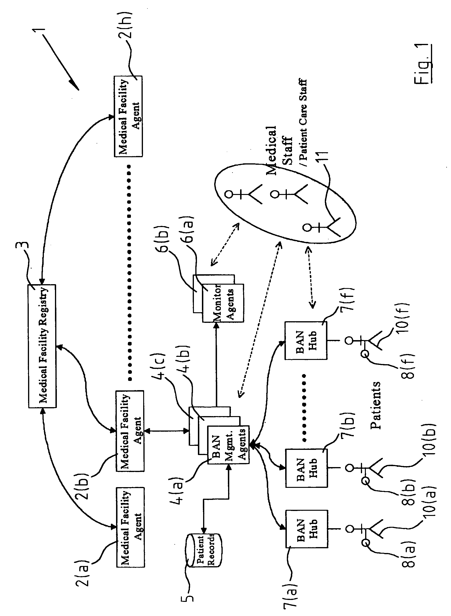
[0062]FIG. 1 is a stylised diagrammatic view of the system,

[0063]FIG. 2 is a flow chart illustrating a training phase,

[0064]FIG. 3 is a flow chart illustrating one aspect of the invention, and

[0065]FIG. 4 is a flow chart illustrating alarm suppression.

[0066]In this specification the term operational remit is used to define the area of responsibility of for example a particular department within a hospital. Such an area could for example be a specified geographical location within a medical facility namely the actual department itself, it could be a transporter for moving a patient around the faculty such as for example hospital trolleys where there would be a department of porters etc., it could be an ambulance for moving the patient out of one hospital to another in which case the medical ...


PUM


Abstract

A patient care distribution and management system is provided. The system allows for the seamless roaming of a patient within a particular medical facility or between medical facilities. The system includes body area network (BAN) management agents which process data within specified parts of a defined operational remit of a medical facility, a BAN hub agent associated with each patient that communicates with a BAN management agent and stores patient data delivered thereto by medical telemetry monitor diagnostic devices (MTMDDs) connected to each patient. The essential feature of the system is that the BAN hub agent has relatively little processing power compared to the BAN management agent which feeds it with patient monitoring rules to monitor the patient condition and to enable the BAN hub agent to set off alarms etc. as required.

Description

[0001]The present invention relates to a method for the collection, analysis and distribution of patient data from a patient stationary or moving within various operational remits of a medical facility to provide patient condition data to patient care staff in accordance with monitoring rules where at least one medical telemetry monitor diagnostic device (MTMDD) is attached to the patient with an associated body area network (BAN) hub agent for the collection and processing of patient diagnostic data when a patient is assigned to one of the operational remits of the medical facility. Further, the invention provides a patient care distribution and management system. Such a specified operational remit, of a medical facility can be one or both of a predetermined geographical area within or outside the medical facility, a transporter moving a patient within or outside the medical facility or indeed a particular patient condition.[0002]It is known, for example, to secure many MTMDD's to ...

Claims


Application Information

Patent Timeline
IPC IPC(8): G06Q50/00G08B23/00G16H10/60
CPCG06F19/3406G06F19/3418G06Q50/24G06F19/345G06F19/3431G16H40/63G16H50/30G16H50/20G16H40/20G16H40/67G16H10/60
Inventor CHAMBERS, DESMONDLYONS, GERARDMADDEN, MICHAELSCHUKAT, MICHAEL
Owner NATIONAL UNIVERSITY OF IRELAND
Learn More