Method and device for controlling and monitoring a position of a holding element

a technology of holding element and position, which is applied in the direction of program control, instruments, electrical devices, etc., can solve the problem of not being able to create such a table economically feasibl

Inactive Publication Date: 2009-02-12
CARL ZEISS NTS LTD
View PDF12 Cites 19 Cited by
  • Summary
  • Abstract
  • Description
  • Claims
  • Application Information

AI Technical Summary

Benefits of technology

[0055]An advantage of the system described herein is that the values stored as discussed elsewhere herein may be used as a diagnostic tool for the device having the holding

Problems solved by technology

Obviously, creating such a table is not economically feasible since recording every addre

Method used


Image

  • Method and device for controlling and monitoring a position of a holding element
  • Method and device for controlling and monitoring a position of a holding element
  • Method and device for controlling and monitoring a position of a holding element

Examples


Embodiment Construction

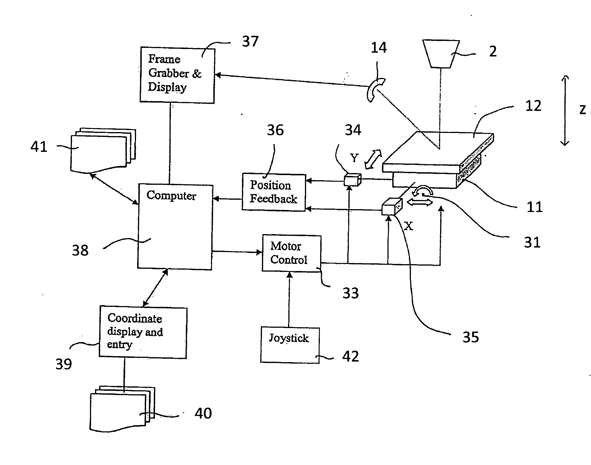
[0067]The system described herein will now be explained with respect to beam devices, in particular to two electron beam devices. One should note that the system described herein is not limited to electron beam devices, but can be arranged and / or used in any device involving the control of a position of a movable part, in particular in any particle beam device.

[0068]FIG. 1 shows a schematic drawing of a scanning electron microscope 1 (hereinafter also referred to as SEM) according to an embodiment of the system described herein. The SEM 1 comprises an electron gun 2 providing electrons. The electron gun 2 is designed as a cathode, preferably as a field emitter. Furthermore, the SEM 1 comprises an extraction electrode 3 and a further electrode 4 designed as an anode. The electrons emitted by the electron gun 2 are accelerated to the potential of the anode due to a potential difference between the electron gun 2 and the electrode 4. The electrode 4 is also one end of a beam guiding tu...


PUM


Abstract

A system for controlling and monitoring a position of a holding element, which is provided to hold a sample to be examined, is disclosed. The system may use a beam device, such as an electron microscope. The system provides for controlling and monitoring a position of a holding element taking into account any errors with respect to irregularities and may include interpolation of possible errors.

Description

TECHNICAL FIELD[0001]This application relates to a method and a device for controlling and monitoring a position of a holding element, which may be provided to hold a sample to be examined, in particular by a beam device such as an electron microscope.BACKGROUND OF THE INVENTION[0002]In devices such as optical microscopes or electron microscopes, it may often be desirable to accurately identify points of interest on a sample which is to be examined by a user with the device. It may also be desirable to record information about points of interest on such a sample so that the points of interest can be reviewed. In some applications, a first device (for example an optical microscope) is used to identify points of interest such as defects on a sample which are then to be examined in detail with a second device such as an electron microscope. Since those defects are rather small, their location must be recorded with high accuracy to be able to find those defects again and to identify the...

Claims


Application Information

Patent Timeline
IPC IPC(8): G21K5/10G01B11/14G01N23/00
CPCG05B19/4086G05B2219/33078G05B2219/37619H01J2237/20292G05B2219/41055H01J37/20H01J2237/202G05B2219/41036
Inventor COOPER, PATRICK
Owner CARL ZEISS NTS LTD
Why Eureka
Try Eureka