Excimer Lamp

a technology of excimer lamps and lamps, which is applied in the direction of discharge tubes/lamp details, discharge tubes luminescnet screens, and multiple discharge path lamps, etc., can solve the problem that the output power of individual excimer lamps is not necessarily sufficient, and achieve the effect of enhancing the output power of excimer radiation

Inactive Publication Date: 2009-02-12
HOYA CANDEO OPTRONICS
View PDF6 Cites 18 Cited by
  • Summary
  • Abstract
  • Description
  • Claims
  • Application Information

AI Technical Summary

Benefits of technology

[0009]Under the circumstances, it is a first object of the present invention to provide an excimer lamp that is enhanced in the radiation output of excimer rays.
[0010]It is a second object of the present invention to provide an excimer lamp that is enhanced in the radiation intensity of excimer rays without causing the cracking or breaking of discharge chambers.
[0035]According to the present invention, there can be provided an excimer lamp of which the excimer-ray radiation output power is enhanced, and according to the present invention, there can be provided an excimer lamp of which the excimer-ray radiation intensity is enhanced while causing none of the cracking and breakage of the discharge chamber.

Problems solved by technology

However, the excimer lamp apparatus described in the above JP-A-2001-135279 is intended to attain a higher output by using a plurality of excimer lamps, and it has a problem that the outputs from the individual excimer lamps thereof are not necessarily sufficient.

Method used


Image

  • Excimer Lamp
  • Excimer Lamp
  • Excimer Lamp

Examples


example 1

Production Example of First Excimer Lamp

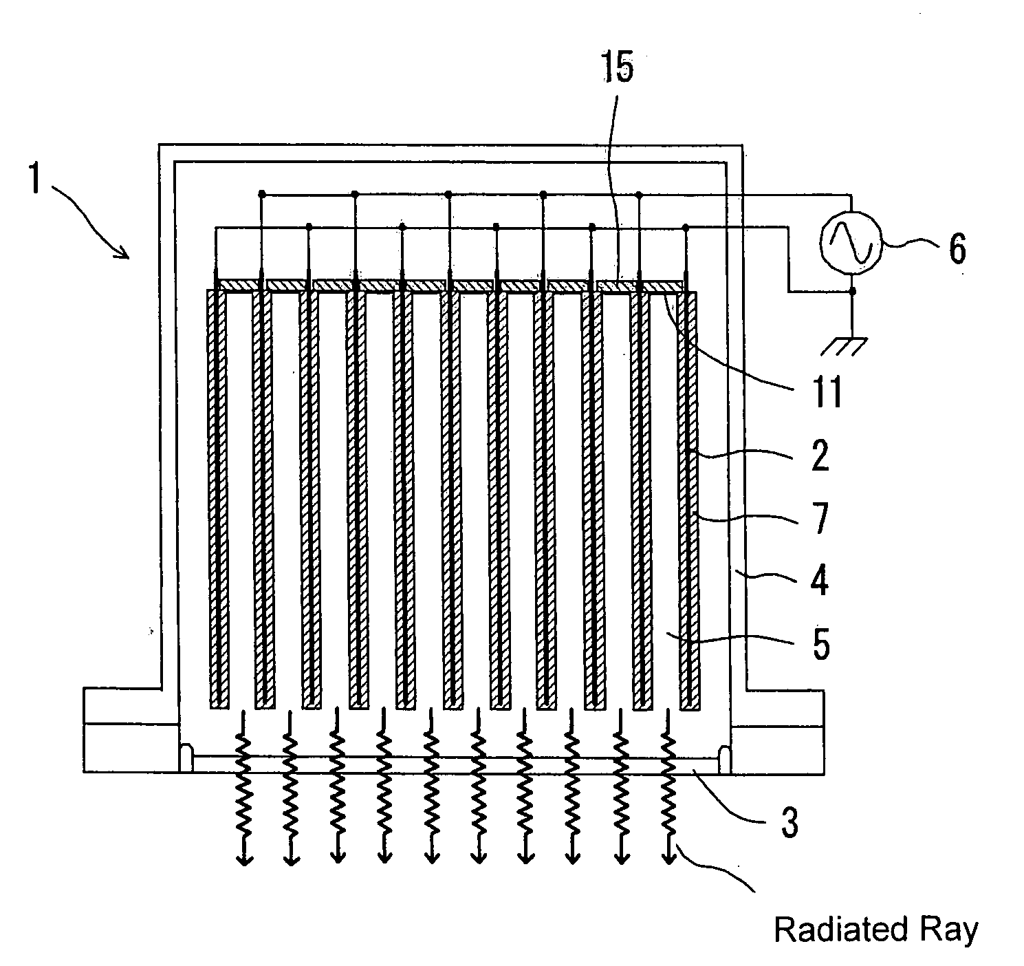
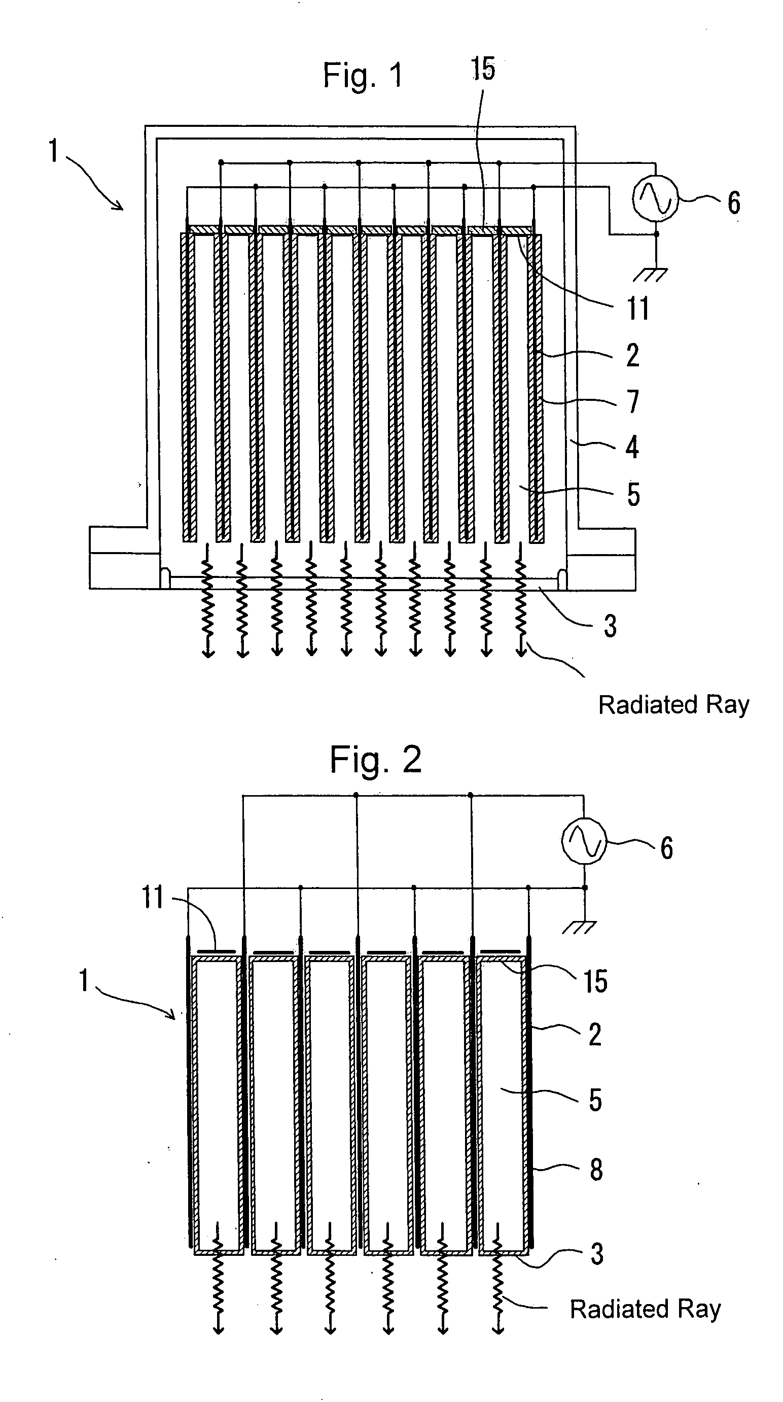
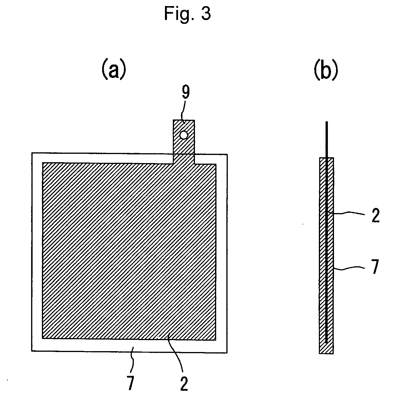
[0134]Fifteen flat-plate electrodes 2 made of aluminum having a form shown in FIG. 3 each were prepared, each of which was surface-polished and had a length of 10 cm, a width of 10 cm and a thickness of 0.5 mm, and they were entirely surface-coated with synthetic quartz glass as a dielectric material except their contacts 9.

[0135]A top plate 15 as shown in FIG. 5(a) was formed with a ceramic plate, and the above flat-plate electrodes 2 made of aluminum and surface-coated entirely with synthetic quartz glass were arranged so as to be opposed to one another in a plate to plate distance of 5 mm. Further, side plates 12 and 13 that were at right angles with the main surfaces of the plate electrodes 2 as shown in FIGS. 4(a) and 4(b) were formed with ceramic plates, to produce a luminous unit having a plurality of box-shaped discharge spaces 5. Although FIGS. 4(a) and 4(b) show five plate electrodes 2, fifteen plate electrodes 2 were actually used.

[...

example 2

Production Example of First Excimer Lamp

[0139]An excimer lamp was produced in the same manner as in Example 1 except that a dielectric multi-layer film formed by alternately stacking magnesium fluoride thin layers and lithium fluoride thin layers was formed on the main surfaces of the dielectric materials 7 as shown in FIG. 5(b), and excimer rays were generated in the same manner as in Example 1.

[0140]The above excimer rays had an output of 310 mW / cm2, and like the result in Example 1, the output that could be obtained was about 5 times the output of an excimer lamp having a nearly equivalent discharge space.

example 3

Production Example of Second Excimer Lamp

[0141]An excimer lamp 101 comprising a luminous unit 102 having a discharge chamber 106 having the form of a parallelepiped as shown in FIG. 6 was produced.

[0142]For producing a luminous unit 102, first, a box-shaped discharge cell 125 having a longitudinal length of 150 mm, a transverse length of 100 mm and a width of 7 mm was prepared and used as a discharge chamber 106. The discharge chamber 106 had a hollow having a longitudinal length of 148 mm, a transverse length of 98 mm and a width of 5 mm, and this hollow was to form a discharge space having a discharge channel length of 5 mm during a discharge. Flat-plate electrodes 105 having a length of 130 mm, a width of 80 mm and a thickness of 1 mm were arranged such that they were placed on both the main surfaces of the discharge chamber 106 one on each. As shown in FIG. 6, the discharge chamber 106 having the thus-arranged plate electrodes 105 was housed in a lamp chamber 104 (diameter 200 m...


PUM


Abstract

The present invention seeks to provide an excimer lamp enhanced in the radiation output of excimer rays, the excimer lamp having at least an optical radiation window provided on the exit side of radiation of rays and a plurality of excimer discharge plates electrodes opposed to one another and having a constitution in which excimer discharge gas present in discharge spaces formed in the said opposed electrodes causes a discharge to radiate excimer rays, said excimer discharge electrodes being flat-plate electrodes, a plurality of said discharge spaces being provided, each of which is between flat-plate electrodes, said optical radiation window being provided in parallel with discharge channels of said discharge spaces.

Description

TECHNICAL FIELD[0001]The present invention relates to an excimer lamp that radiates excimer ray.BACKGROUND ART[0002]For curing a coating composition or for carrying out surface washing or surface modification of a semiconductor wafer, a glass substrate, etc., it is conventional practice to radiate excimer rays to an object to be treated, by means of an excimer lamp.[0003]As a method for applying excimer rays, a method using dielectric barrier discharge is known, and as the above excimer lamp, there is known an excimer lamp that is described in JP-A-2001-135279.[0004]In the excimer lamp described in JP-A-2001-135279, a nearly co-axial dual circular tube is formed by co-axially arranging hollow quartz glass tubes having different diameters in cross section, a gas for excimer discharge is filled in a hollow portion formed between the two quartz glass tubes, an external electrode is wound around the outer surface of the outer-side quartz glass tube, an internal electrode is wound around...

Claims


Application Information

Patent Timeline
IPC IPC(8): H01J63/04
CPCH01J65/046H01J61/12H01J61/92H01J65/00
Inventor OHSHIMA, HIROYOSHIKOBAYASHI, NORIO
Owner HOYA CANDEO OPTRONICS
Why Eureka
Try Eureka