Laser safety system with beam steering

a safety system and laser technology, applied in the field of laser safety systems, can solve the problems of laser radiation damage to an unprotected human eye, eye damage considerable, and potential harm to both people and equipmen

Active Publication Date: 2009-02-12
TELESIS TECH
View PDF50 Cites 13 Cited by
  • Summary
  • Abstract
  • Description
  • Claims
  • Application Information

AI Technical Summary

Benefits of technology

[0014]A laser safety system according to the present invention provides a system that is utilized to determine the presence, integrity and focus of a laser focusing lens before a laser system is enabled. The system increases the safety of people and objects that may be contacted by laser radiation that is misdirected toward them due to missing, damaged or unfocused laser focusing lenses by reducing the risk thereof. The laser safety system can also identify missing or damaged beam steering mirrors or devices, and may also be employed to provide target recognition.
[0024]Another object of the present invention is to provide a method for safely positioning a laser system including the steps of determining a safe orientation of a beam steering device for laser processing and associating a plurality of signal sources and signal sensors with the beam steering device and a work surface in a signal sensing orientation, wherein the method further includes the steps of orienting the beam steering device such that the signal sensors may detect a signal from their respective signal sources when the laser beam steering device is in the predetermined safe orientation, and detecting the signal from the signal sources by the signal sensors, and wherein a laser system is enabled when all of the signal sensors detect signals from their respective signal sources, or disabled when less than all of the signal sensors detect signals from their respective signal sources and a perceivable alarm is produced when the laser system is disabled.

Problems solved by technology

The lasers used in many of these devices and systems are often capable of producing energy output that is potentially harmful to both people and equipment.
Further, some forms of laser radiation can damage an unprotected human eye even before it has time to react to the exposure.
This may lead to considerable physical damage to the eye, such as cutting or burning, and can also result in temporary or permanent vision impairment or blindness.
At other focal lengths however, the laser radiation may be harmful even at long distances from the source.
Another potential danger associated with lasers is that of chemical vapors, dust or melted liquids that may be formed in the area where the laser interacts with a work surface, such as in laser welding or scribing.
The harmful properties of these chemicals may adversely affect nearby persons if inhaled or otherwise transferred to the body.
Class II systems are considered a hazard for direct long-term ocular exposure.
Class III system emission levels are ocular hazards for direct exposure and may be hazardous to skin at longer exposure times. Class IV systems are the most hazardous and pose a danger to eyes and skin upon direct, as well as indirect exposure such as that resulting from scattered, diffused or reflected radiation.
However, for reasons such as costs and performance requirements, laser systems are often operated at more dangerous classification levels.
For example, providing a sealed enclosure for a laser system inside which the laser operation takes place may represent the safest scenario, but may be impractical due to cost and size where the laser system and work piece are large.
Further, portable laser systems, by their very nature, may not function optimally with the safety systems available in the art.
Due to the size of the structure an enveloping enclosure is not feasible.
In contrast, where the surface has numerous features such a shroud would be ineffective, because it would be difficult or impossible to sufficiently conform the shroud to the work piece.
Another problem in a laser system is the difficulty in determining the direction in which invisible laser radiation is aimed and what it is striking.
It may be difficult with these systems to determine if the beam is always aimed at, and focused on, the desired target.
If a laser beam is not aimed properly, it may be reflected or scattered off of the target and strike somewhere else, potentially causing damage.
Further, if the desired target is misaligned, has a hole in it or is missing altogether, damage to equipment and / or personnel could occur.
Yet another possible hazard derives from the laser system itself.
If the focusing lens is missing or damaged in some way the beam may be unfocused and scattered, refracted or reflected to some other unspecified target.

Method used


Image

  • Laser safety system with beam steering
  • Laser safety system with beam steering
  • Laser safety system with beam steering

Examples


Embodiment Construction

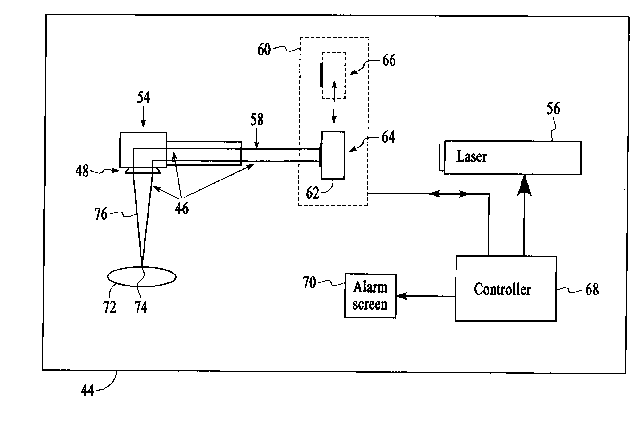
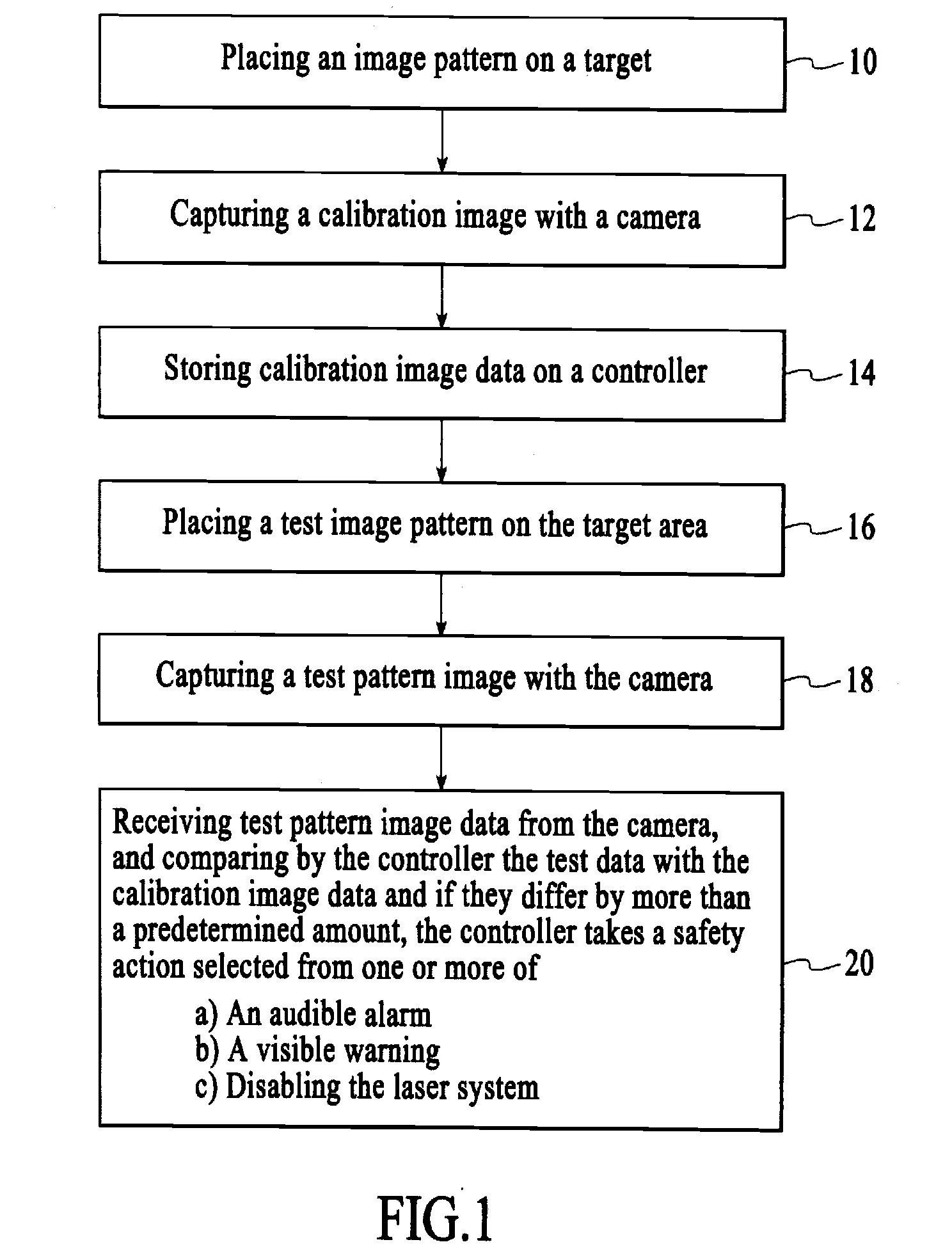
[0051]A method of the present invention is illustrated generally in reference to FIG. 1 of the drawing. A safety system is described for the purpose of reducing the possibility of a laser beam being misdirected and causing damage to persons or property. According to block 10, a calibration image pattern is placed on a target area of a laser system. The term “image pattern” will refer to any form of visible pattern, including a printed or scribed pattern, picture, etc. The image pattern can also be a non-material image, such as a projected light image for example. The adjective “calibration” in “calibration image pattern” is used to indicate that at this point in the method, the system has been determined to be in acceptable working condition, and the image data to be collected at this point referred to as image calibration data is to be used as a reference for future image data, termed “test data” or “image test data” taken prior to operation of the system. The calibration procedure...


PUM

PropertyMeasurementUnit
areaaaaaaaaaaa
energyaaaaaaaaaa
timeaaaaaaaaaa

Abstract

A laser safety system providing a system for checking the presence, focus and integrity of a laser beam focusing lens is disclosed. The laser safety system checks the focusing lens properties by capturing an image of a target by viewing the target through the focusing lens from along the laser beam path. An initial, known good, image is compared to an image captured immediately before enablement of the laser beam source to determine if the focusing lens is present, focused and is not damaged. The system may also utilize a mask projected onto the target as well as a low-power visible light laser directed along the path of the processing laser to determine the focusing lens properties. The system can also provide target recognition.

Description

RELATED APPLICATIONS[0001]The present invention claims priority from U.S. Provisional Patent Application Ser. No. 60 / 797,102 filed May 2, 2006, which is incorporated herein by reference.BACKGROUND OF THE INVENTION[0002]1. Field of the Invention[0003]The present invention relates generally to safety systems for lasers, and more particularly to a method and apparatus for testing laser beam focus and beam alignment prior to operating the laser system, and for taking a safety action if the system is not in proper working condition.[0004]2. Brief Description of the Prior Art[0005]Many types of laser-based devices and systems, having a wide range of applications in fields such as manufacturing, research, communications and medicine have become increasingly well-known and commercially available. The lasers used in many of these devices and systems are often capable of producing energy output that is potentially harmful to both people and equipment.[0006]The potential dangers associated wit...

Claims


Application Information

Patent Timeline
Patent Type & Authority Applications(United States)
IPC IPC(8): H04N7/18G01J1/20
CPCB23K26/032B23K26/034B23K26/0884H01S3/005B23K2201/006G01M11/0221H01S3/0014B23K26/428B23K26/707B23K26/0648B23K2101/006
Inventor HARRISON, MICHAELFERRARIO, JOSEPH D.MESROPYAN, ASHOT
Owner TELESIS TECH
Why Eureka
Try Eureka