
Tire shape measuring system

a technology of shape measurement and tire, which is applied in the direction of image analysis, structural/machine measurement, instruments, etc., can solve the problems affecting the image quality of the tire, etc., to achieve the effect of reducing the processing load of image processing and high image capture ra

Active Publication Date: 2009-02-12
KOBE STEEL LTD
View PDF6 Cites 47 Cited by
  • Summary
  • Abstract
  • Description
  • Claims
  • Application Information

AI Technical Summary

Benefits of technology

[0018]Accordingly, it is an object of the present invention to provide a tire shape measuring system capable of, when measuring the shape of a tire surface by capturing an image of a line of light (an image of a light section line) emitted to the surface of the relatively rotating tire and detecting the shape using the captured image and a light-section method, acquiring a clear image of a light section line without increasing the intensity of line light even when the image of the light section line is captured at a sufficiently high rate (e.g., 4000 frames or more per second). It is a further object of the present invention to provide a tire shape measuring system capable of reducing processing load of image processing required for detecting the light section line so as to support such a high image capture rate.

Problems solved by technology

However, in the inspection method for detecting a defective tire shape on the basis of measurement of the tire shape using a point-measuring sensor, the number of the sensors arranged and the time available for inspection are limited.
Accordingly, the entire surface shape of the tire to be measured cannot be measured at one time, and therefore, some defective tires may pass through the inspection process.
Thus, the possibility of a line of light emitted to the surface of the tire being diffusely reflected is relatively low.
However, if the intensity of the line of light is increased, the black tire that easily absorbs the light may be damaged by heat.
Accordingly, a measuring system is increased in size and cost.
Still furthermore, the maintainability disadvantageously decreases.
In addition, in order to capture the image of a light section line in a circumferential direction of the rotating tire with sufficient spatial resolution within a limited time allowable for product inspection, the capture rate (the number of image captures per unit time) cannot be decreased to that sufficient for capturing a clear image of the line of light.
However, if images are captured at a high rate of 4000 frames per second, it is difficult to obtain a clear image of the light line using a technology described in Japanese Unexamined Patent Application Publication No. 11-138654.
However, because of a limitation of the processing power of a practical MPU that can be used as a component of an inspection system (a measuring system) for detecting a tire having a defective shape, it is difficult for the MPU to perform the extraction process of a light section line on the basis of a captured image within 1 / 2000 to 1 / 4000 seconds after the image (the luminance information about an image for one frame) is captured.
As a result, the production efficiency of a tire is decreased.

Method used


Image

  • Tire shape measuring system
  • Tire shape measuring system
  • Tire shape measuring system

Examples


Embodiment Construction

[0099]Exemplary embodiments of the present invention are described below with reference to the accompanying drawings. It is to be understood that following embodiments are only for illustration purposes, which shall not be construed as limitation to the scope of the present invention. Similar numbering will be used in describing similar or equivalent components in the following embodiments.

[0100](1)

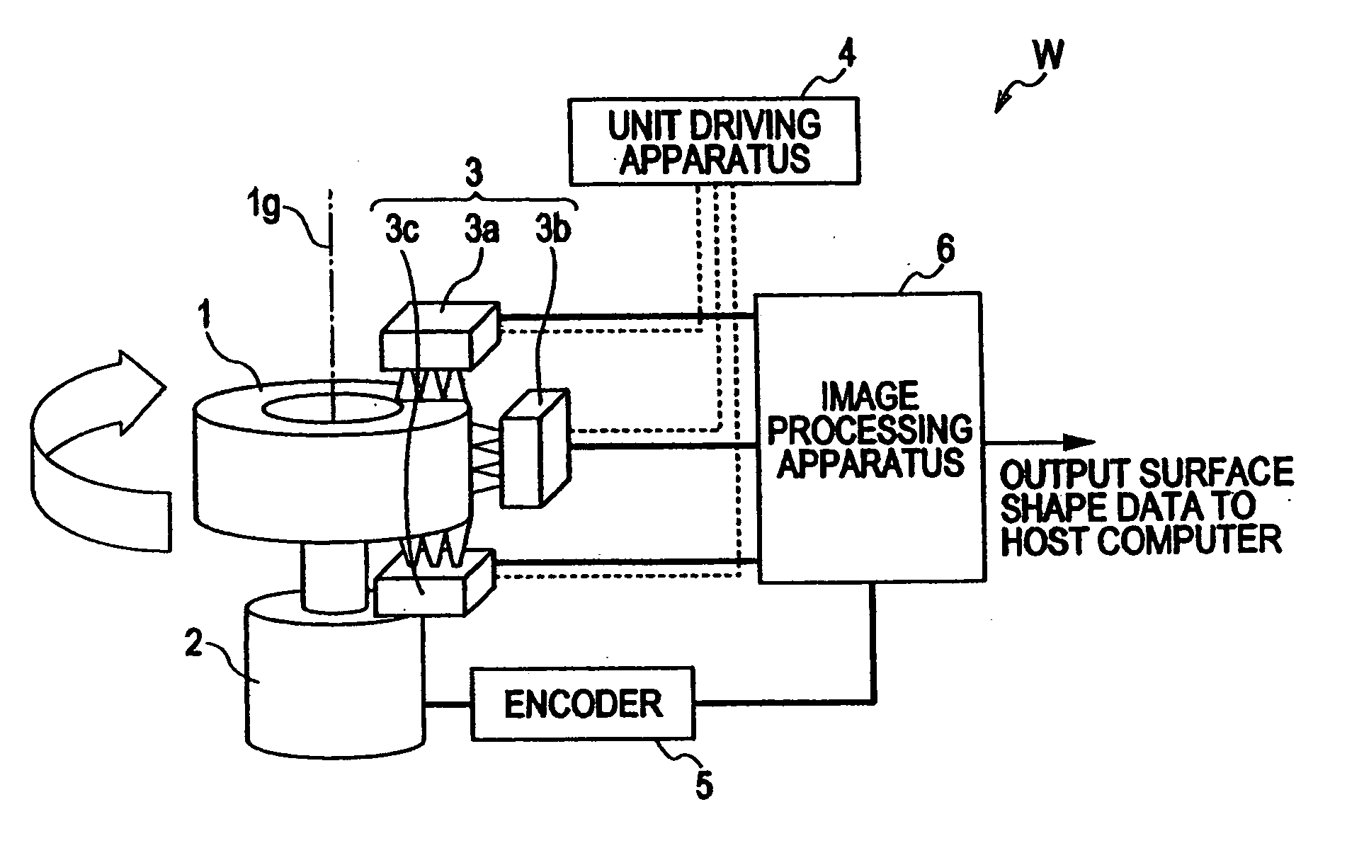
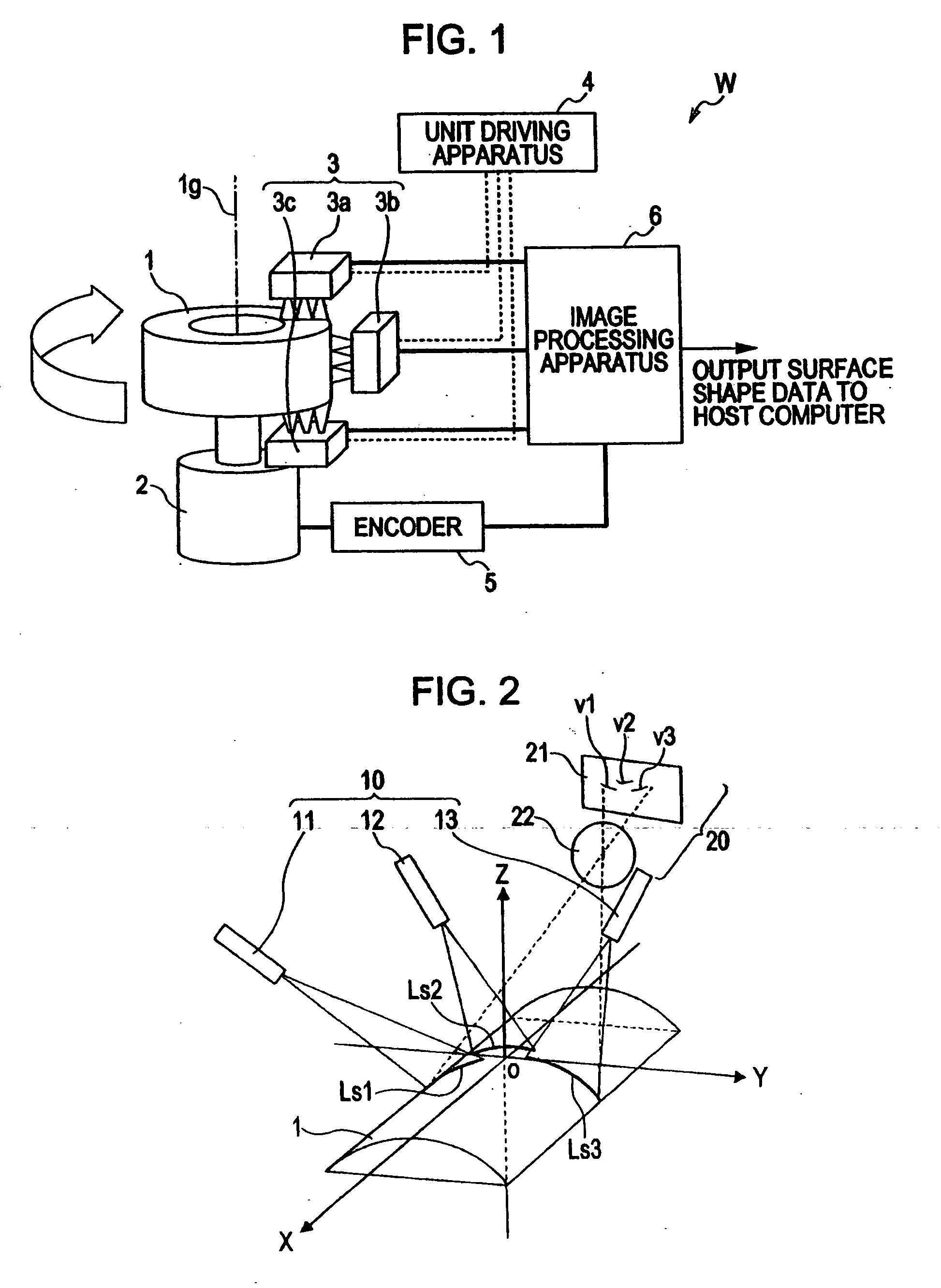
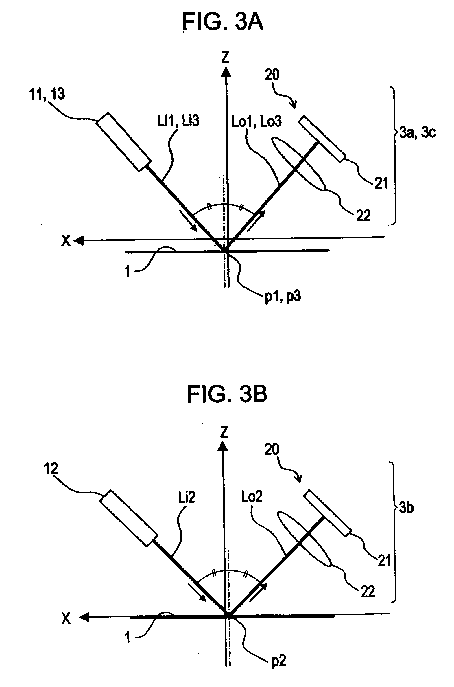
[0101]FIG. 1 is a schematic illustration of an exemplary structure of a shape measuring system W for a tire according to an embodiment of the present invention. FIG. 2 is a three-dimensional schematic illustration of an arrangement of a light source and a camera in a sensor unit included in the shape measuring system W. FIGS. 3A and 3B are schematic illustrations of an arrangement of a line light source and a camera in a sensor unit included in the tire shape measuring system when viewed in a particular direction (a Y-axis direction). FIGS. 4A to 4C are schematic illustrations of an arran...


PUM


Abstract

A tire shape measuring system measures a surface shape on the basis of an image of a line of light (a light section line) emitted to a surface of a relatively rotating tire using a light-section method. The shape measuring system includes a light projector for emitting a plurality of lines of light onto a tire surface in directions different from a direction in which the height of the surface is detected so as to form a plurality of separate light section lines and a camera for capturing images of the light section lines in directions in which chief rays of the lines of light are specularly reflected by the tire surface. The shape measuring system individually detects the coordinates of the light section lines from images of pre-defined independent image processing target areas for each captured image and calculates the distribution of the surface height using the detected coordinates.

Description

CROSS REFERENCES TO RELATED APPLICATIONS[0001]The present invention contains subject matter related to Japanese Patent Application No. 2007-204266 filed in the Japanese Patent Office on Aug. 6, 2007 and No. 2007-208353 filed in the Japanese Patent Office on Aug. 9, 2007, the entire contents of which are incorporated herein by reference.BACKGROUND OF THE INVENTION[0002]1. Field of the Invention[0003]The present invention relates to a tire shape measuring system for capturing an image of a line of light (an image of a light-section line) emitted to the surface of a relatively rotating tire and detecting the surface shape of the tire by detecting the shape using the captured image and a light-section method.[0004]2. Description of the Related Art[0005]In general, in order to control the quality of products in factories, the surface shape of a product (the distribution of the height of the surface of a product) needs to be contactlessly measured at high speed.[0006]Tires are manufacture...

Claims


Application Information

Patent Timeline
IPC IPC(8): G01B11/24
CPCG01B11/2522G06T7/0057G01M17/027
Inventor TAKAHASHI, EIJISAKODA, NAOKAZUMORIMOTO, TSUTOMU
Owner KOBE STEEL LTD
Learn More