Multi channel radiometer imaging method and system

a radiometer and multi-channel technology, applied in the field of security systems, can solve the problems of inability to post-fabrication circuit element tuning, inability to meet the requirements of security personnel, so as to increase the number of pixels and thereby resolution, facilitate security personnel's operation and synchronization, and increase the functional test yield and performance of the system

Inactive Publication Date: 2009-02-12
MICROSEMI CORP ANALOG MIXED SIGNAL GRP LTD
View PDF27 Cites 27 Cited by
  • Summary
  • Abstract
  • Description
  • Claims
  • Application Information

AI Technical Summary

Benefits of technology

[0032]Another very important object of the invention is to provide a single pixel subassembly to increase functional test yield and performance of the system.
[0033]Still another important object of the invention is to provide a radiometer having the ability to increase the number of pixels and thereby resolution, using the same radiometer housing and other electrical hardware components.
[0034]Another very important object of the invention is to provide a security system that has the ability to successfully perform without exposing security personnel and innocent by-standers to any potential threat or danger from a concealed object.
[0035]Another important object of the invention is to provide a security system that is non-invasive to the individual being searched for concealed objects.
[0036]Still another very important object of the invention is to provide an improved security system that is easy for security personnel to operate and to synchronize.
[0037]Another object of the invention is to provide an improved security system to identify non-metallic concealed objects on an individual such as explosives.

Problems solved by technology

An inherent deficiency of this type of security system is the fact that it exposes not only the security personnel to danger, but also other individuals (e.g., travelers in an airport) in the vicinity of the security system to the dangers posed by such concealed objects.
Although there are advantages to using a MMIC, including low fabrication costs, there are also significant disadvantages.
One significant disadvantage is that post fabricating tuning of circuit elements is not practical.
More complex circuit designs require multiple iterations before acceptable performance is achieved and MMIC fabrication requires extremely long iteration times. Further, MMIC research and development requires specialized equipment such as wafer probes, probe stations, and wire bonders.
Also, synthesized signal sources or spectrum analyzers makes circuit measurements difficult.
The relatively high adsorption of the millimeter wave band makes long distance wireless communication not practical.
Accordingly, a shortcoming of the prior art is that if an LNA fails as part of a subassembly of a series of LNAs, that results in the loss of the entire subassembly.
However, the radiometer of Vaidya is not expandable to increase the number of pixels and thereby the resolution of an image.
A shortcoming of this prior art is that it comprises a series of LNAs wherein one failed LNA of the series results in a completely failed subassembly and resultant increased fabrication costs.

Method used


Image

  • Multi channel radiometer imaging method and system
  • Multi channel radiometer imaging method and system
  • Multi channel radiometer imaging method and system

Examples


Embodiment Construction

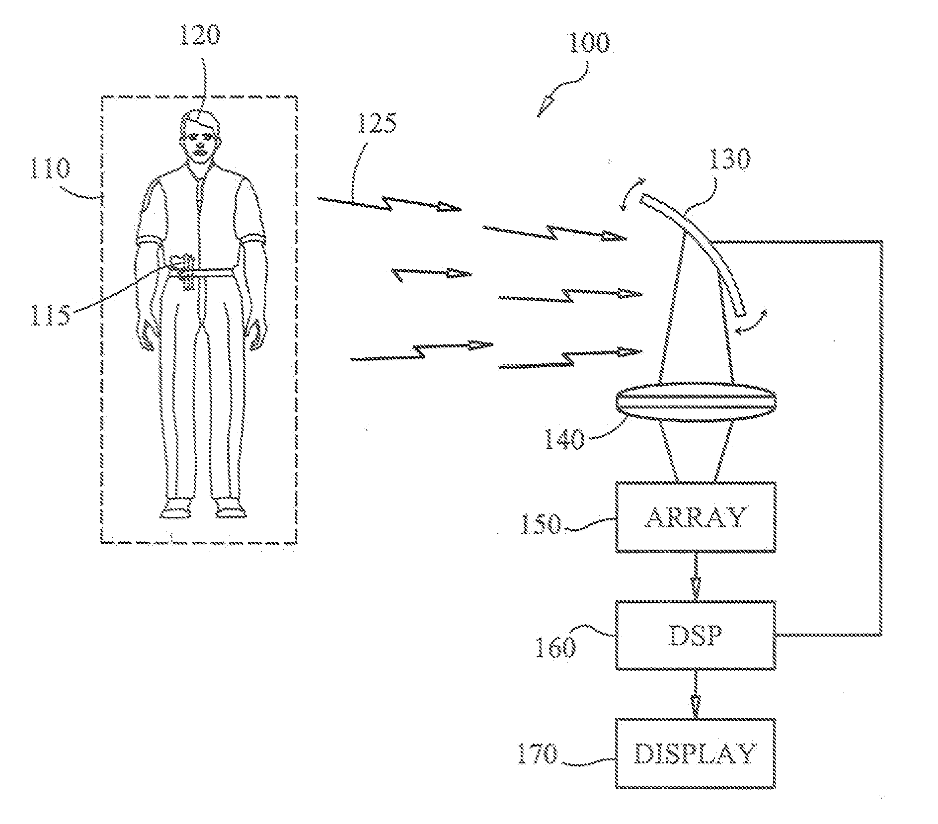
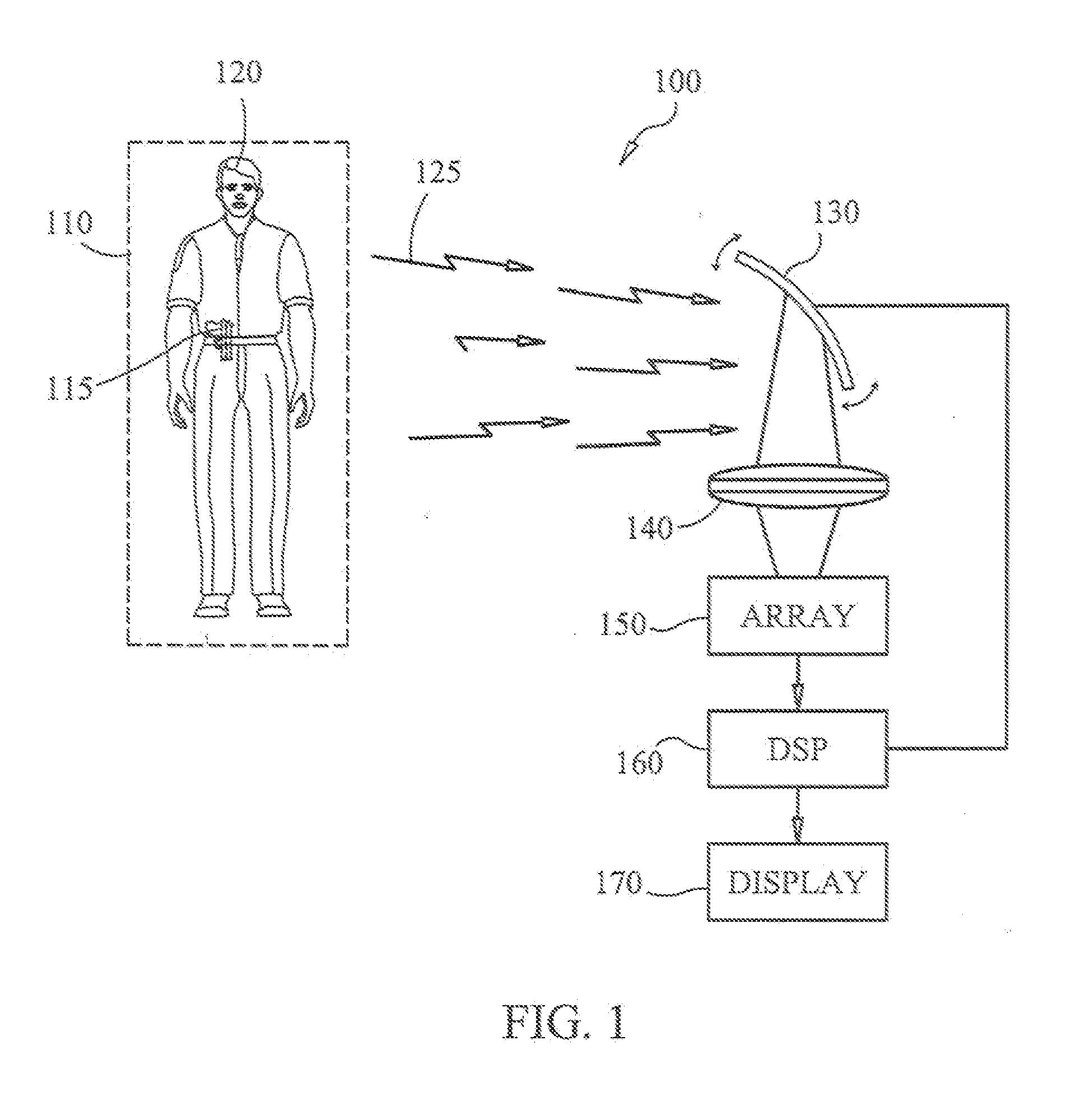
[0051]Referring to FIG. 1, an imaging system 100 is shown in accordance with the present invention. An imaging zone 110 is formed by the area prescribed by scanning apparatus 130 that reflects millimeter wave energy 125 radiating from imaging zone 110. Scanning apparatus 130 is constrained to oscillate in a vertical plane to reflect millimeter wave energy 125. Millimeter wave energy 125 is reflected through an optical lens 140 to focus the millimeter wave energy 125 to an array of radiometers 150. A digital signal processor 160 correlates the movement of scanning apparatus 130 to specific x-y coordinates in the imaging zone 110. As described below, algorithms process the signals received by array 150 to form a composite image on display 170 showing the location of concealed objects on an individual 120.

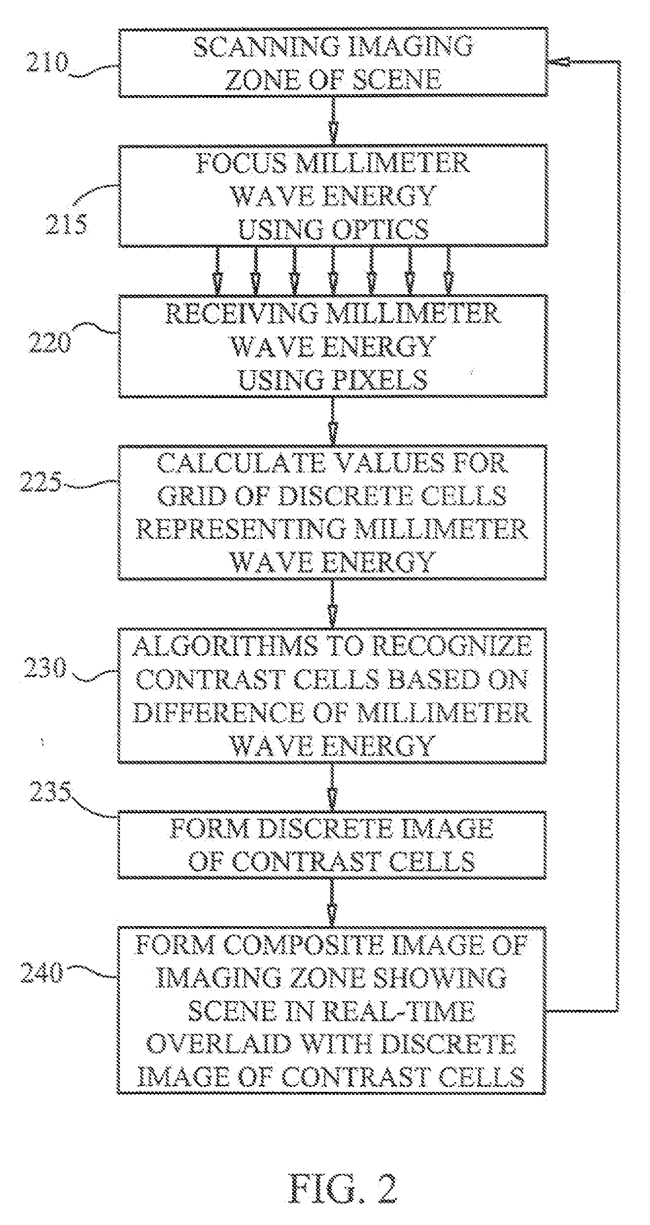
[0052]FIG. 2 shows a flow chart illustrating logic that may be used to implement preferred embodiments of the method of the present invention. As shown in FIG. 2, imaging zone is scan...


PUM


Abstract

The invention provides for an expandable multi channel radiometer imaging method and system. The imaging system includes a scanner for reflecting millimeter wave energy emanating from a pre-determined scene. The millimeter wave energy is focused to a focal plane array using an optical lens and a multi channel radiometer receives the millimeter wave energy. The focal plane array is formed by a plurality of pixels that each includes a single low noise amplifier. The number of pixels of the focal plane array is expendable to increase the resolution of a millimeter wave image. A virtual grid of cells is formed representing different values of millimeter wave energy within the imaging zone. Algorithms calculate differences of millimeter wave energy between cells of said virtual grid to display a composite image to identify concealed objects on an individual.

Description

BACKGROUND OF THE INVENTION[0001]1. Field of the Invention[0002]The present invention relates generally to security systems, and more specifically to a multi channel radiometer that is expandable to increase the number of pixels and utilizes single pixel subassemblies to increase the functional test yield performance.[0003]2. Description of the Prior Art[0004]Security systems can be found at transportation centers such as airports, train stations or at other public facilities such as courthouses, government buildings, or public schools. One of the principal concerns of operators of security systems is the need to protect security personnel and other individuals (e.g. the general public) in the course of conducting a search of a person for concealed objects. The concealed objects that present a danger are weapons, explosives, contraband and other similar items.[0005]Prior art security systems include metal or chemical residue detectors that require security personnel to be in proximi...

Claims


Application Information

Patent Timeline
Patent Type & Authority Applications(United States)
IPC IPC(8): G06K9/00
CPCH01Q21/064G01V8/005
Inventor DALY, ROBERTBARRANTES, ERNESTO
Owner MICROSEMI CORP ANALOG MIXED SIGNAL GRP LTD
Why Eureka
Try Eureka