Double-core optical fiber

a technology of optical fiber and core, applied in the field of double core optical fiber, can solve the problems of optical loss in the connection with short wavelength region multimode optical fiber, increase in bit error rate, etc., and achieve the effect of stable single-mode transmission

Inactive Publication Date: 2009-02-12
NIPPON TELEGRAPH & TELEPHONE CORP
View PDF8 Cites 13 Cited by
  • Summary
  • Abstract
  • Description
  • Claims
  • Application Information

AI Technical Summary

Benefits of technology

[0031]According to the present invention, the first material and the second and third materials provided on the outer circumference thereof enable one optical fiber to have two different aperture ratios of an aperture ratio of an optical fiber for single mode transmission in the first wavelength region (for example, long wavelength region) and an aperture ratio of optical fiber for multimode transmission in the second wavelength region (for example, short wave

Problems solved by technology

When the “double clad fiber” returns from the bended state to a linear state, the signal light propagated in multimode in the first cladding couples with the core, interferes with the signal light or

Method used


Image

  • Double-core optical fiber
  • Double-core optical fiber
  • Double-core optical fiber

Examples


first embodiment

[0057]FIG. 4A is a refractive index profile of a double core fiber according to this embodiment, and FIG. 4B is a cross sectional diagram of the double core optical fiber having the refractive index profile of FIG. 4A.

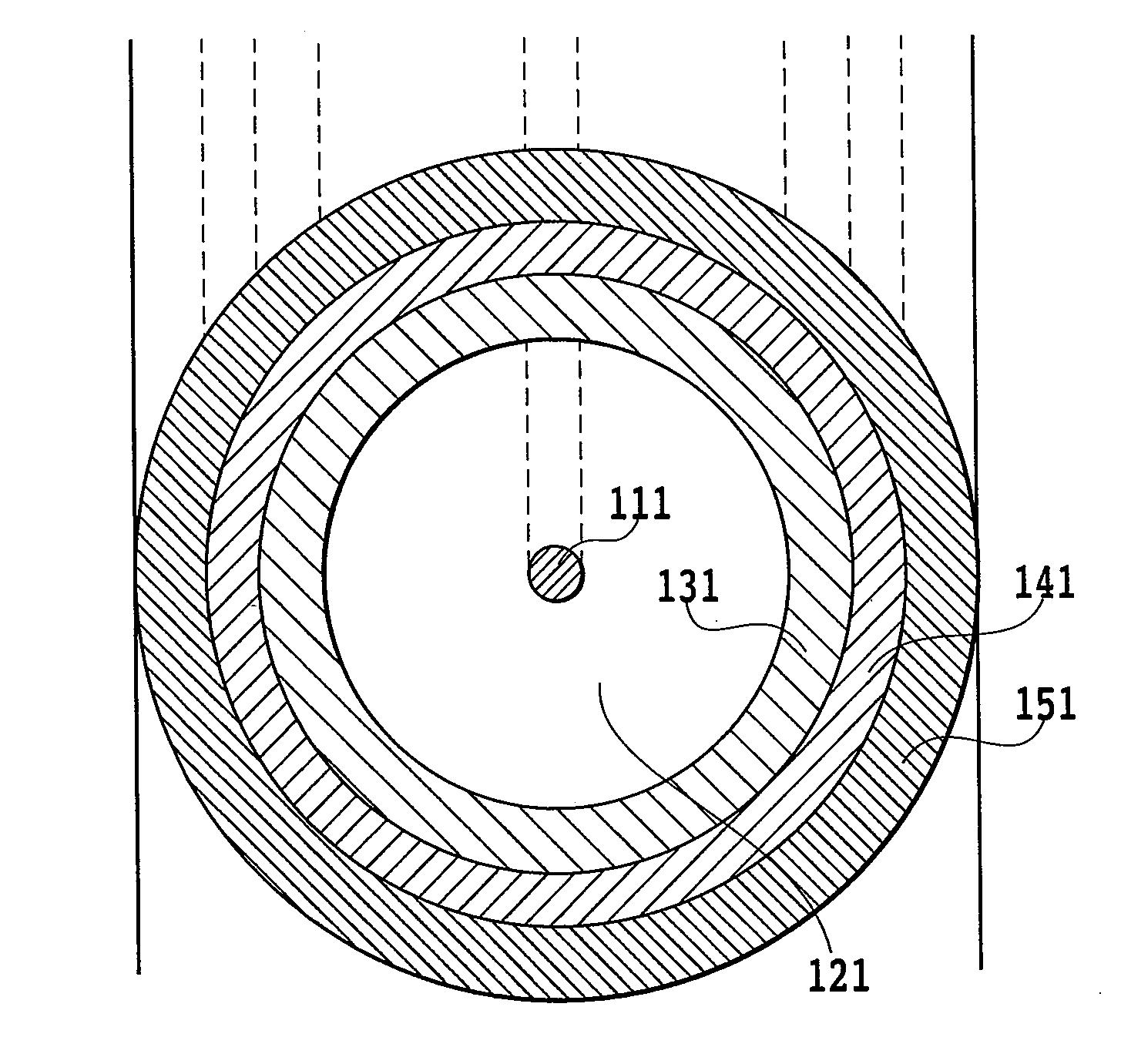
[0058]In FIG. 4B, a core 111 as the first material for single mode transmission is provided at the center, and a first cladding 121 as the second material, a second cladding 131 as the third material, a third cladding 141 as the fourth material, and a fourth cladding 151 constituted of a polymer resin are sequentially provided on the outside of the core 111. Note that, as the core 111 and the first to third claddings, materials generally used for optical fibers, e.g., quartz glass and organic matters such as polymer and acrylic, may be used.

[0059]In this embodiment, the core 111 is formed of quartz doped with at least one of elements Ge, P, Sn, and B. The first cladding 121 is formed of pure quartz. Further, the second cladding 131 and the third cladding 141 are formed...

second embodiment

[0090]In this embodiment, the direction of the bend of the optical fiber is determined in advance, and the refractive index is made low in a region on the outer circumference side of the optical fiber when bent in the determined direction, which includes a part of the outer circumference portion (surface portion) of the material (second material) formed to cover the core for single mode signal light and excludes the core.

[0091]FIG. 6A is a refractive index profile of the double core fiber according to this embodiment, and FIG. 6B is a cross sectional diagram of the double core optical fiber having the refractive index profile of FIG. 6A.

[0092]In FIG. 6B, the core 111 as the first material for single mode transmission is provided in the center, and a first cladding 227 as the second material, a second cladding 231 as the third material, and a third cladding 241 constituted of polymer resin are sequentially provided on the outside of the core 111. Note that, as the core 111 and the fi...


PUM


Abstract

A double core optical fiber is provided, in which single mode signal light and multimode signal light can be transmitted and a multimode transmission of the signal light guided through the core can be reduced even when the optical fiber is bent. The double core optical fiber of the present invention includes a core (111) arranged on a central axis of the optical fiber and having a refractive index (112), a first cladding (121) arranged on the outer circumference of the core (111) and having a refractive index (122) smaller than the refractive index (112), and a second cladding arranged on the outer circumference of the first cladding (121) and having a refractive index (132) smaller than the refractive index (122). The core (111) functions as a core for single mode transmission, the core (111) and the first cladding (121) function as a core for multimode transmission, the first cladding (121) function as a cladding for the core for single mode transmission, and the second cladding (132) functions as a cladding for the core for multimode transmission.

Description

TECHNICAL FIELD[0001]The present invention relates to a double core optical fiber, and more specifically relates to a double core optical fiber capable of transmitting a single mode (for example, long wavelength region single mode) optical signal and a multimode (for example, short wavelength region multimode) optical signal simultaneously.BACKGROUND ART[0002]As known technology of propagating single mode propagating light and multimode propagating light having different wavelengths with the same optical fiber, there is a “double clad fiber.” A first cladding for simultaneously guiding output light from a pump laser is arranged outside a core doped with a rare earth element for amplifying signal light. The double clad fiber is structured with a second cladding arranged on the outer circumference of the first cladding, which is arranged on the outer circumference of the core. The output light from the pump laser couples with the first cladding, and propagates in multimode while inter...

Claims


Application Information

Patent Timeline
IPC IPC(8): G02B6/036
CPCG02B6/02042G02B6/02047G02B6/0283G02B6/03661G02B6/03616G02B6/03627G02B6/03605
Inventor TANOBE, HIROMASASAKAI, YOSHIHISA
Owner NIPPON TELEGRAPH & TELEPHONE CORP
Why Eureka
Try Eureka