Eureka AIR delivers breakthrough ideas for toughest innovation challenges, trusted by R&D personnel around the world.

On-demand hydrogen gas generation device with pressure-regulating switch

a hydrogen gas generation and switch technology, applied in the direction of reactant parameter control, electrical apparatus, fuel cells, etc., can solve the problems of hydrogen generation and storage, components occupying space, and high-pressure hydrogen being potentially unsa

Inactive Publication Date: 2009-02-12
ROVCAL
View PDF19 Cites 24 Cited by
  • Summary
  • Abstract
  • Description
  • Claims
  • Application Information

AI Technical Summary

Benefits of technology

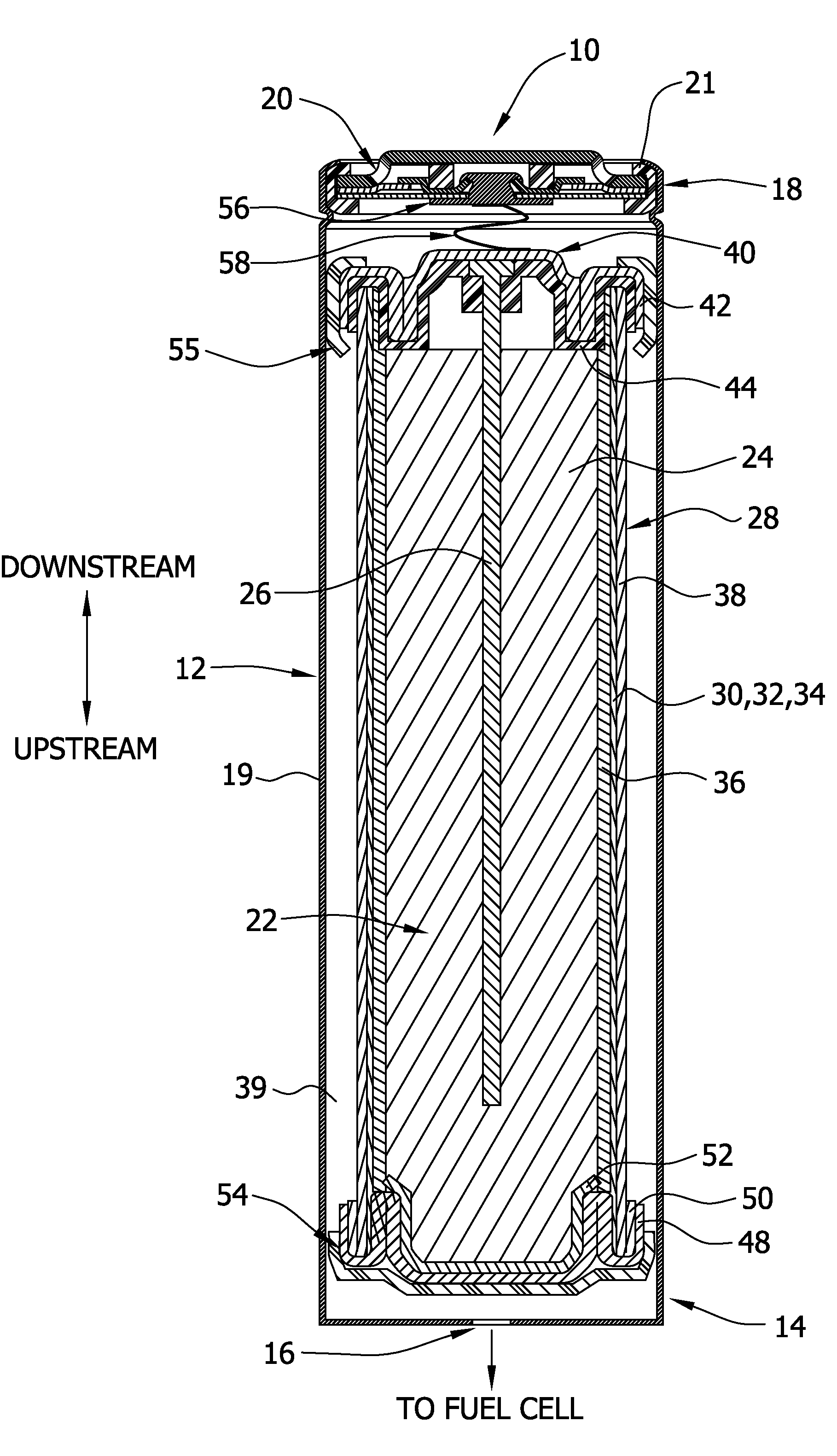
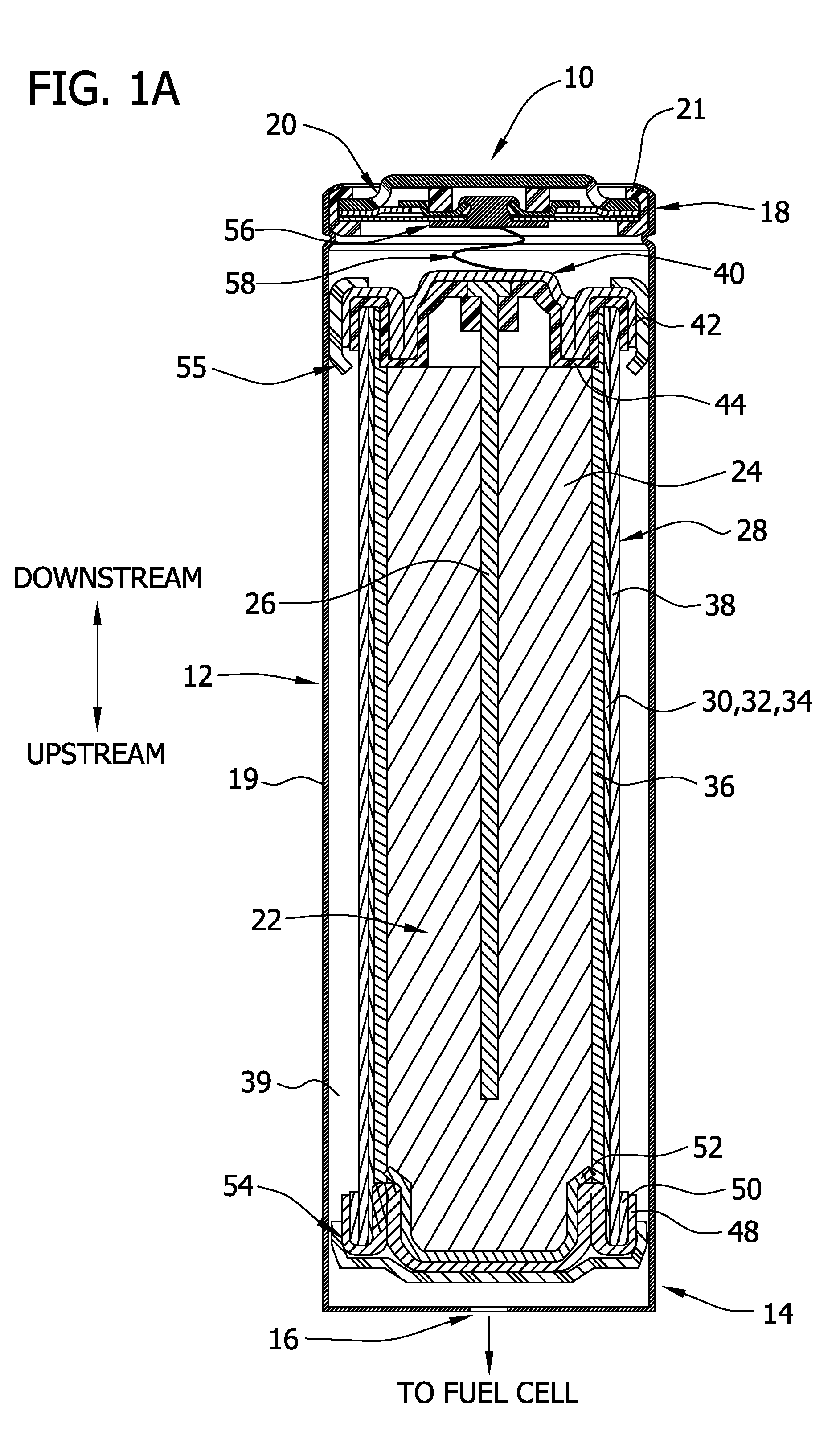
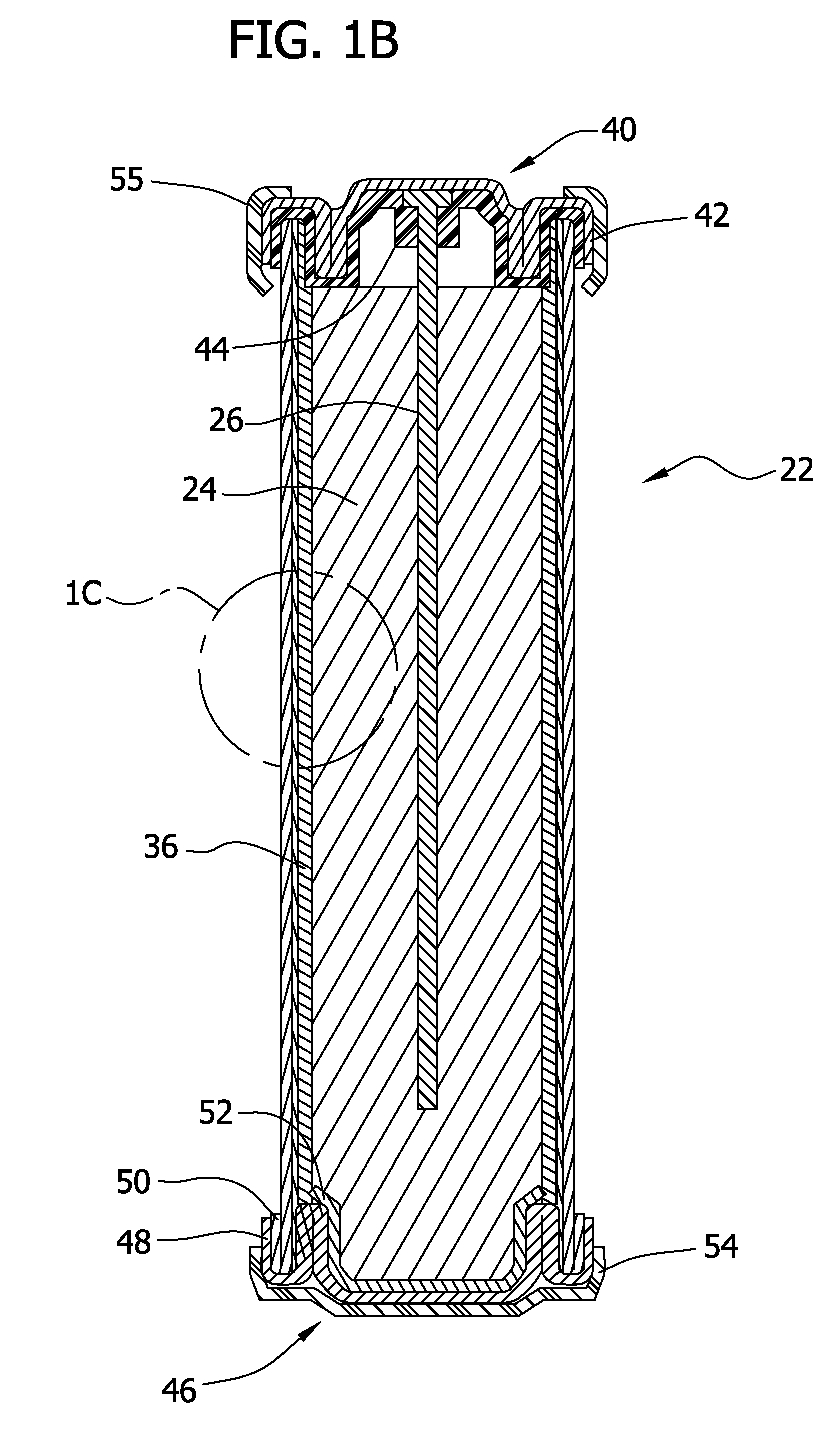
[0009]Briefly, therefore, the present disclosure is directed to an on-demand hydrogen gas generation device that comprises: (a) a cell comprising a means for generating an average flow of hydrogen gas of at least about 0.1 cubic centimeter / minute / cubic centimeter of fuel volume for a period of time of at least about 1 hour; and, (b) a switching mechanism in communication with the cell comprising the hydrogen gas generation means, the switching mechanism regulating the generation of hydrogen gas therein, the switching mechanism comprising a moveable member that is operable to repeatedly and reversibly move between a first position and a second position in response to a pressure differential created by said cell of less than 30 psig, wherein (1) in the first position an electrical current passes through the switching mechanism which enables the generation of hydrogen gas from said cell, and (2) in the second position resistance in the switching mechanism to the electrical current passing therethrough increases to reduce the rate of hydrogen gas generation from said cell.

Problems solved by technology

The generation and storage of hydrogen however, has significant challenges, in that it must be economically viable and safe to store and transport, in order to make it a useful alternative to traditional fuels.
Additionally, thicker / bulkier components such as a portable pressure tank, and high pressure plumbing leading to the fuel cell, may be required to contain hydrogen that is much above atmospheric pressure.
These components take up space that could otherwise be used for the fuel cell, and more particularly the hydrogen fuel itself.
Furthermore, stored high pressure hydrogen is potentially unsafe (particularly for air transportation), while a hydrogen generator that only produces hydrogen when the fuel cell is in operation minimizes the amount of stored hydrogen, making it intrinsically safer.
The size and weight restrictions for portable applications tend to limit the design options to “passive” systems (both fuel cell and fuel generator), which are systems that do not require pumps, flow meters, pressure regulators, etc. that are generally acceptable in stationary applications.
Such an approach may not be preferred in some applications or uses, however, because it requires a large and heavy or bulky external hydrogen source to be available for recharging the fuel cell.
Additionally, the carrying around or transport of a device which includes a container of pressurized hydrogen gas creates undesirable safety concerns.
However, such an approach may also not be preferred in some applications or uses for a number of reasons, including the fact that it requires the user to carry or transport a device that includes a container of a flammable liquid.
The direct electrolysis of water using electrical energy generally requires expensive catalysts as well as a source of electrical energy.
Furthermore, in addition to proper selection of the means by which hydrogen gas is generated (i.e., selection of a source which provides maximum hydrogen generation per unit volume), a challenge exists to efficiently maximize the transport or evolution of the hydrogen gas, once generated, out of the generator and into the fuel cell for consumption, in order to maximize energy output.
Since the hydrogen generator device is in communication with the fuel cell and the plumbing leading up to the fuel cell, this carry-over of corrosive liquid is highly undesirable.
Additionally, any loss of liquid from the generator device results in less available liquid for hydrogen generation, which is also highly undesirable.
Any additional incoming moisture with the fuel (e.g. hydrogen gas) only increases the burden on the system, which can become a significant problem with small systems used in portable consumer devices.

Method used


Image

  • On-demand hydrogen gas generation device with pressure-regulating switch
  • On-demand hydrogen gas generation device with pressure-regulating switch
  • On-demand hydrogen gas generation device with pressure-regulating switch

Examples


example 1

Positive Electrode Preparation

[0186]This is an example that illustrates the preparation of a suitable positive electrode material, and more specifically illustrates the deactivation of Raney Nickel 3202 and the resulting use thereof to prepare a catalyst layer and ultimately a gas management electrode for use in accordance with the present disclosure:

[0187]A. Deactivation of Raney Nickel

[0188]Raney Nickel is spontaneously combustible in air when it is dry. While it may be possible to process it safely in a wet form, for the purposes of this example, a procedure to deactivate it was used based on literature information (see, e.g., “Novel Methods of stabilization of Raney-Nickel catalyst for fuel cell electrodes”, M. A. Al-Saleh, et. Al., Journal of Power Sources 72 (1998) pp 159-164). The procedure is described in greater detail below.

[0189]Material / Equipment List: Raney 3202 Nickel, slurry in water (Sigma Aldrich product #510068); 5% hydrogen peroxide solution, diluted from 50% solu...

example 2

Correlation Between Hydrogen Gas Generation Rate and Current

[0201]The hydrogen gas generation rate was observed to correlate well with the current measured during generation of gas. Once this correlation was established for different currents, in the interest of simplicity and speed all the reported results were based on current measurements.

[0202]A cylindrical cell design of Example 4 (i.e., the Bobbin-type cell design), further detailed below, was used to make the noted correlation. Individual generator cells were discharged at a fixed current of 350 mA and 650 mA respectively, and the hydrogen generation rates were measured by the displacement of a column of water in a graduated burette. An additional experiment was performed that involved a single cell that was tested at various constant current levels in a stepped manner. A comparison of the theoretical (calculated) vs. the actual measured gas generation rate is shown in the graph presented in FIG. 16, which indicates this corr...

example 3

Spiral-Wound Cell Design

[0203]For this example, a D-size alkaline cell can was used. A spiral wound design is generally known to one skilled in the art to enable higher discharge rates (i.e., discharge currents, and hence gas generation rates in this application) than a typical bobbin cell design. The positive electrode comprised a compressed nickel foam material which was post-plated with nickel to produce a more active nickel surface than the as-received Ni foam (as further detailed herein below). The spiral wound D cell design consisted of a layered arrangement of two positive electrode sheets and three anode pouches made up of the hydrophilic gas impermeable, liquid permeable layer material. The anode pouches comprised 1.5 wraps of 1 mil M2000 and were filled with a gelled Zn anode. The filled anode pouches were about 2 mm thick, to enable a higher anode rate and efficiency than a “bobbin” design used in typical alkaline batteries.

[0204]As noted, the positive electrode for H2 ev...


PUM


Abstract

The present disclosure generally relates to an on-demand hydrogen gas generation device, suitable for use in a fuel cell, which utilizes water electrolysis, and more particularly galvanic cell corrosion, and / or a chemical hydride reaction, to produce hydrogen gas. The present disclosure additionally relates to such a device that comprises a switching mechanism that has an electrical current passing therethrough and that repeatedly and reversibly moves between a first position and a second position when exposed to pressure differential resulting from hydrogen gas generation, in order to (1) alter the rate at which hydrogen gas is generated, such that hydrogen gas is generated on an as-needed basis for a fuel cell connected thereto, and / or (2) ensure a substantially constant flow of hydrogen gas is released therefrom. The present disclosure additionally or alternatively relates to such an on-demand hydrogen gas generation device that comprises a gas management system designed to maximize the release or evolution of hydrogen gas, and in particular dry hydrogen gas, therefrom once it has been formed, thus maximizing hydrogen gas output. The present disclosure is still further directed to a fuel cell comprising such an on-demand hydrogen gas generation device, and in particular a fuel cell designed for small-scale applications.

Description

CROSS REFERENCE TO RELATED APPLICATIONS[0001]This patent application claims priority from U.S. Provisional Patent Application 60 / 951,609 filed on Jul. 24, 2007, the entire contents of which is incorporated herein by reference.FIELD OF THE DISCLOSURE[0002]The present disclosure generally relates to an on-demand hydrogen gas generation device, suitable for use with a fuel cell, which utilizes electrolysis, and more particularly galvanic corrosion of one or more metals or metal alloys, and / or a chemical hydride reaction, to produce hydrogen gas. The present disclosure additionally relates to such a device that comprises a switching mechanism that has an electrical current passing therethrough, and that rapidly and repeatedly (or reversibly) moves between a first position and a second position when exposed to a pressure differential resulting from hydrogen gas generation, in order to alter the rate at which hydrogen gas is generated, such that hydrogen gas is generated on an as-needed b...

Claims


Application Information

Patent Timeline
IPC IPC(8): H01M8/00
CPCH01M8/04089H01M8/04216H01M8/0438Y02E60/50H01M8/065H01M8/0656H01M8/04895
Inventor VU, VIETDAVIDSON, GREGORY J.ROM, CRAIGBUSHONG, WILLIAM C.
Owner ROVCAL
Why Eureka
Eureka Blog
Learn More