
Method and apparatus for sealing a glass package

a glass package and sealing technology, applied in the direction of transportation and packaging, manufacturing tools, discharge tube luminescnet screens, etc., can solve the problems of insufficient weight of the substrate in and of itself to facilitate a good seal, and the great effort is made to provide a hermetic package, etc., to achieve the effect of improving the seal quality of the glass packag

Inactive Publication Date: 2009-02-19
CORNING INC
View PDF21 Cites 17 Cited by
  • Summary
  • Abstract
  • Description
  • Claims
  • Application Information

AI Technical Summary

Benefits of technology

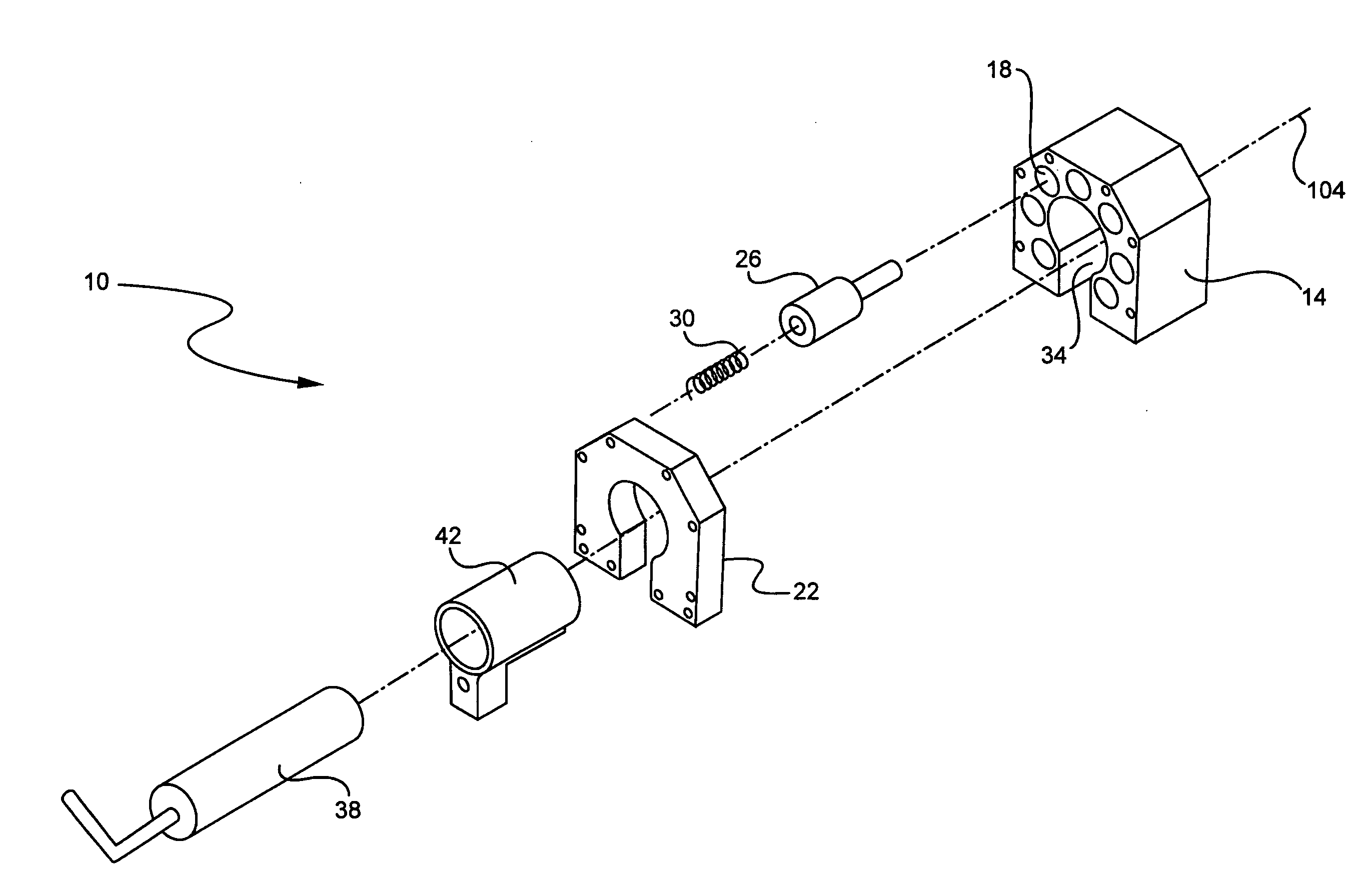
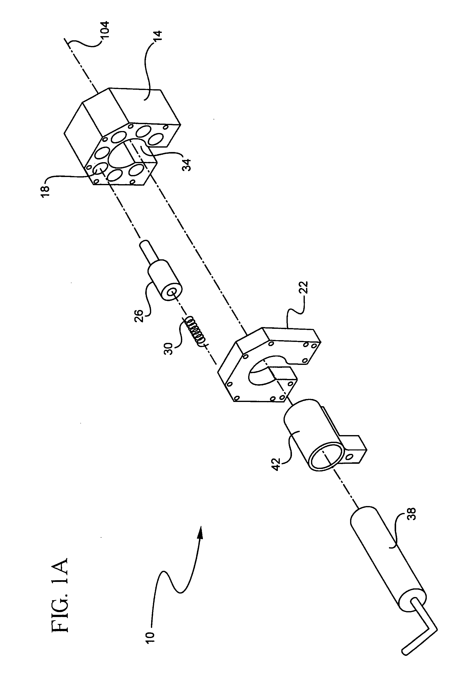
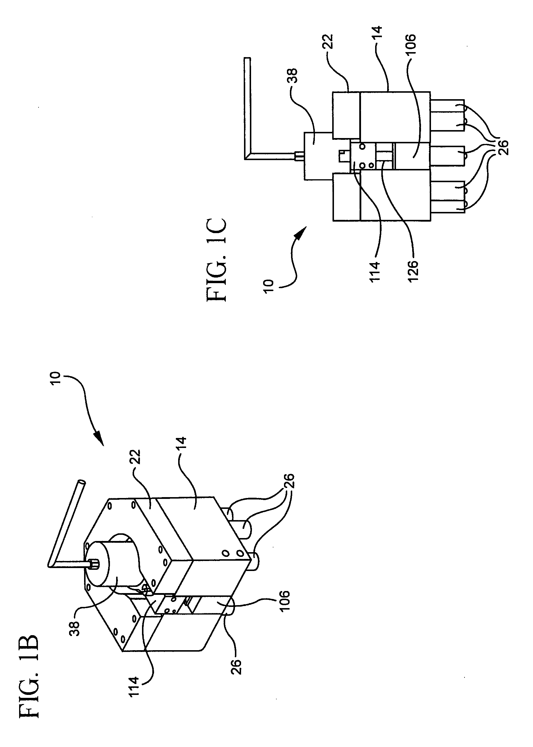
[0012]An apparatus and method are disclosed that can improve the seal quality of a glass package, and in particular a glass package comprising one or more organic light emitting diode devices. In one broad aspect the present invention is used to apply a force against an assembly comprising first and second glass substrates, and including a sealing material disposed therebetween. Simultaneous with the application of the force, a beam of radiation is used to irradiate the sealing material, thereby connecting the first substrate to the second substrate according to the nature of the sealing material. For example, if the sealing material is an adhesive, such as an epoxy adhesive, the radiation beam may cure the adhesive. If the sealing material is a glass-based frit, the radiation beam can be used to heat and soften the frit to form the seal. Both the laser beam and the applied force are traversed over the length of the sealing material to form a sealed glass package. Preferably, the glass package is hermetically sealed such that oxygen and / or water do not penetrate the seal at more than about 10−3 cc / m2 / day and / or 10−6 g / m2 / day, respectively. Thus, the life of an organic light emitting diode (OLED) device that may be disposed between the first and second substrates and encircled by the sealing material may advantageously be extended.
[0013]The force is applied by bearing elements that contact and press against the glass assembly. The bearing elements are biased by a restoring force, such as a spring or gas pressure, so that once contact with the assembly is made (e.g. one of the glass substrates), further movement of the apparatus toward the assembly applies a force against the assembly. The bearing elements may be adapted to roll across the surface of a substrate or to slide across the surface of the substrate. Preferably, the force is applied against the assembly in proximity to the point on the assembly at which the radiation beam impinges. That is, it is preferably that a plurality of bearing elements generally encircle the point at which the beam impinges so that the force is relatively uniformly applied to the substrate(s) and transmitted to the sealing material. Thus, contact between the sealing material and the substrates can be improved by causing the sealing material to spread against the substrates. Moreover, the force applied by the method and apparatus disclosed herein can mitigate against unevenness in the height of the sealing material above the substrate on which the sealing material may be dispensed. This unevenness can result in a poor seal between the substrates.
[0014]In some embodiments, the radiation source is slidably connected to a housing, such as through a collet, the position of the housing thus being adjustable relative to the radiation source. In some embodiments, the position of the radiation source may be fixed, and the beam of radiation directed by optical elements, such as mirrors, attached to the housing so that the beam traverses the assembly without the need for moving the radiation source.

Problems solved by technology

Therefore, great effort is made to provide a hermetic package to contain the OLED devices.
However, adhesives, such as various epoxies, tend to have unacceptable leakage rates for long device life, thereby requiring a desiccant to be disposed within the sealed glass package to absorb moisture and / or various gases which may penetrate the seal, or which may be generated during curing of the adhesive seal.
However, the weight of the substrate in and of itself is insufficient for facilitating a good seal.
Simply placing the aligned sheets of glass beneath the laser and sealing with the laser will produce a seal, but one that has narrow patches as well as delamination defects, which are both caused by irregularities in the dispensed sealing material (e.g. frit).
These artifacts of the sealing process have a severely detrimental effect on the life and performance of an OLED device disposed between the substrates.
This unevenness can result in a poor seal between the substrates.

Method used


Image

  • Method and apparatus for sealing a glass package
  • Method and apparatus for sealing a glass package
  • Method and apparatus for sealing a glass package

Examples


experiment 1

[0065]To illustrate the sealing process, an experiment was conducted using a substrate assembly 46 comprising first and second glass substrates. Each of the first and second substrates was approximately 0.7 mm in thickness. The first substrate did not include OLED devices. The second substrate included nine frit walls formed in the shape of rectangular walls or frames that had been deposited onto the second substrate and pre-sintered. The width of the frit wall was approximately 2 mm at the surface of the second substrate. The second substrate was placed overtop the first substrate with the pre-sintered frit disposed between the two substrates. Apparatus 10 was thereafter used to seal each of the nine frit walls with a predetermined force per ball bearing. The laser power was 23 watts at a nominal wavelength of about 900 nm. The laser (i.e. apparatus 10) was traversed over each frit wall. The experiment was repeated for 9 substrate assemblies: The results are shown in Table 1 for 6 ...


PUM

PropertyMeasurementUnit
Massaaaaaaaaaa
Forceaaaaaaaaaa

Abstract

An apparatus for sealing a glass package by applying a force to a glass assembly while simultaneously irradiating a sealing material disposed between the two glass substrates with a beam of radiation. The applied force is translated in unison with the radiation beam. The radiation cures and / or melts the sealing material, depending upon the sealing material. The applied force beneficially improves contact between the glass substrates and the sealing material during the sealing process, therefore assisting in achieving a hermetic seal between the substrates.

Description

BACKGROUND OF THE INVENTION[0001]1. Field of the Invention[0002]This invention relates to a method and an apparatus for sealing a glass package, and in particular sealing an organic light emitting diode display device with radiation.[0003]2. Technical Background[0004]Flat panel display devices, such as liquid crystal and plasma display devices for use in televisions, continue to replace cathode ray tube display devices as the display of choice for a broad array of applications, from cell phones to televisions.[0005]More recently, organic light emitting diode (OLED) display devices have made progress in the market place. Unlike LCD displays, which utilize a liquid crystal layer to alternately pass and block a light source, and plasma displays which emit light from a charged gas, OLED displays utilize an essentially solid state array of organic light emitting diode devices to generate light, each organic light emitting diode comprising one or more layers of an organic material sandwic...

Claims


Application Information

Patent Timeline
IPC IPC(8): B65B51/10C03B29/00
CPCB32B17/06C03C27/06Y10T29/53174Y10T29/49171Y10T29/5313H01L51/5237H10K59/8722H10K50/8426
Inventor BOTELHO, JOHN W.GENTILE, MARGARET HELENMORGAN, KENNETH SPENCERPOWELL, WILLIAM ROBERTZHANG, LU
Owner CORNING INC
Learn More