Planar magnetic device and power supply IC package using same

Active Publication Date: 2009-02-19
KK TOSHIBA +1
View PDF9 Cites 58 Cited by
  • Summary
  • Abstract
  • Description
  • Claims
  • Application Information

AI Technical Summary

Benefits of technology

[0010]According to the above-described circumstances in which a large amount of magnetic material must be used because of low magnetic permeability, an object of the present invention is to achieve a planar magnetic device, such as a thin inductor, by use of an arrangement structure that can produce a high inductance effectively.

Problems solved by technology

More specifically, it has been found that the magnetic permeability in a magnetic field generated in the coil is not increased effectively to achieve a thin inductor exhibiting a high inductance unless the winding interval of the coil and the maximum particle size of the magnetic powder are adjusted to establish a predetermined relationship so that the magnetic powder fill the spaces between the windings of the coil, or unless the magnetic powder contained in the magnetic layer comes in direct contact with the planar coil or comes close to the planar coil at a distance of 1 μm or less without forming an insulating layer between the planar coil and the magnetic layers over and under the planar coil.

Method used


Image

  • Planar magnetic device and power supply IC package using same
  • Planar magnetic device and power supply IC package using same
  • Planar magnetic device and power supply IC package using same

Examples


examples 1 to 5

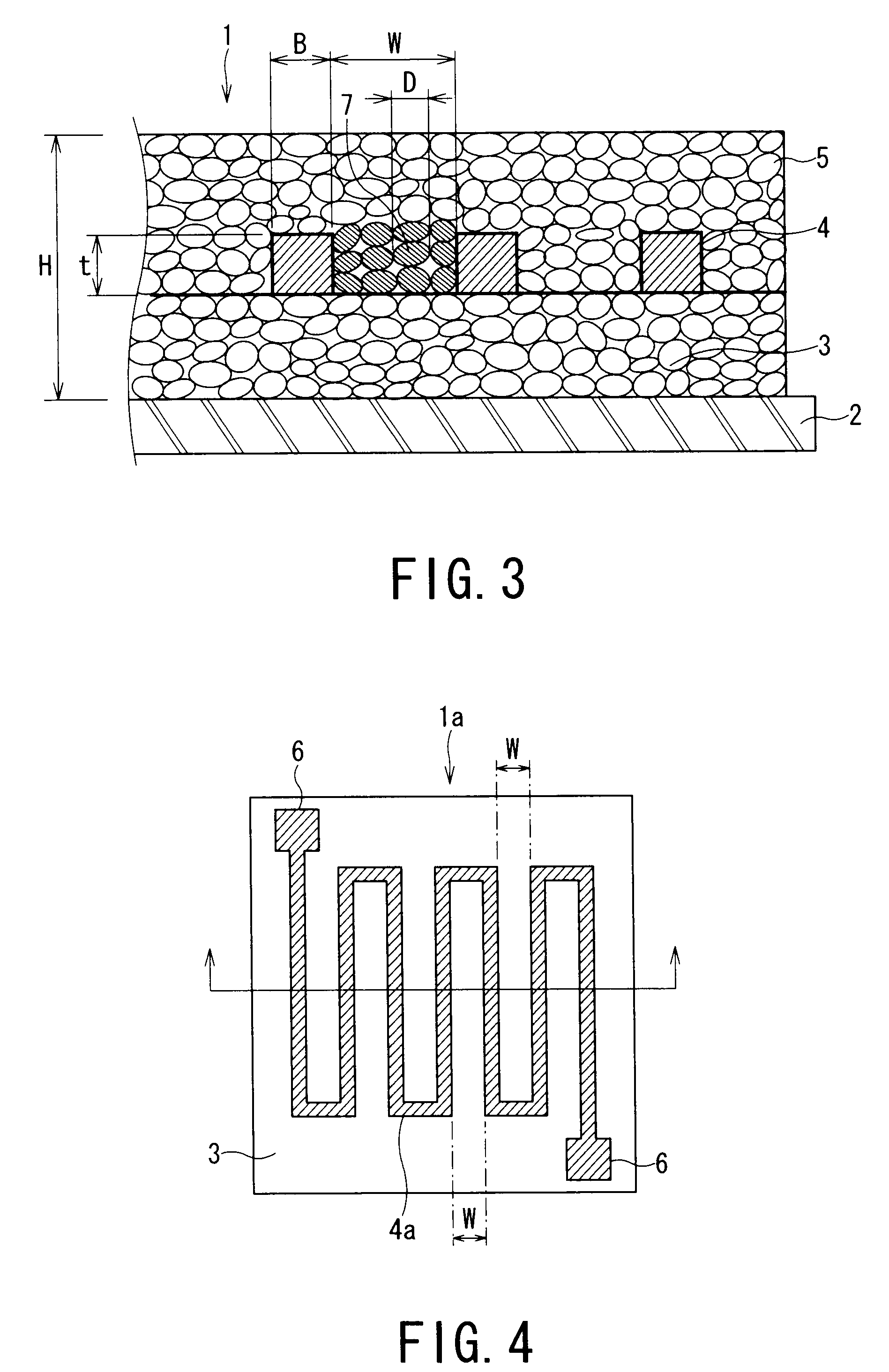
[0048]Magnetic material powders each having any one of the compositions shown in Table 1 were screened to prepare magnetic powders having maximum particle sizes L (maximum diameter) and average particle sizes D that are shown in Table 1. The maximum particle size shown in Table 1 is represented by the value of the opening of the screen. Each magnetic powder was mixed with an ethyl cellulose solution in a proportion of 16% by mass relative to the magnetic powder to prepare a magnetic powder paste, respectively.

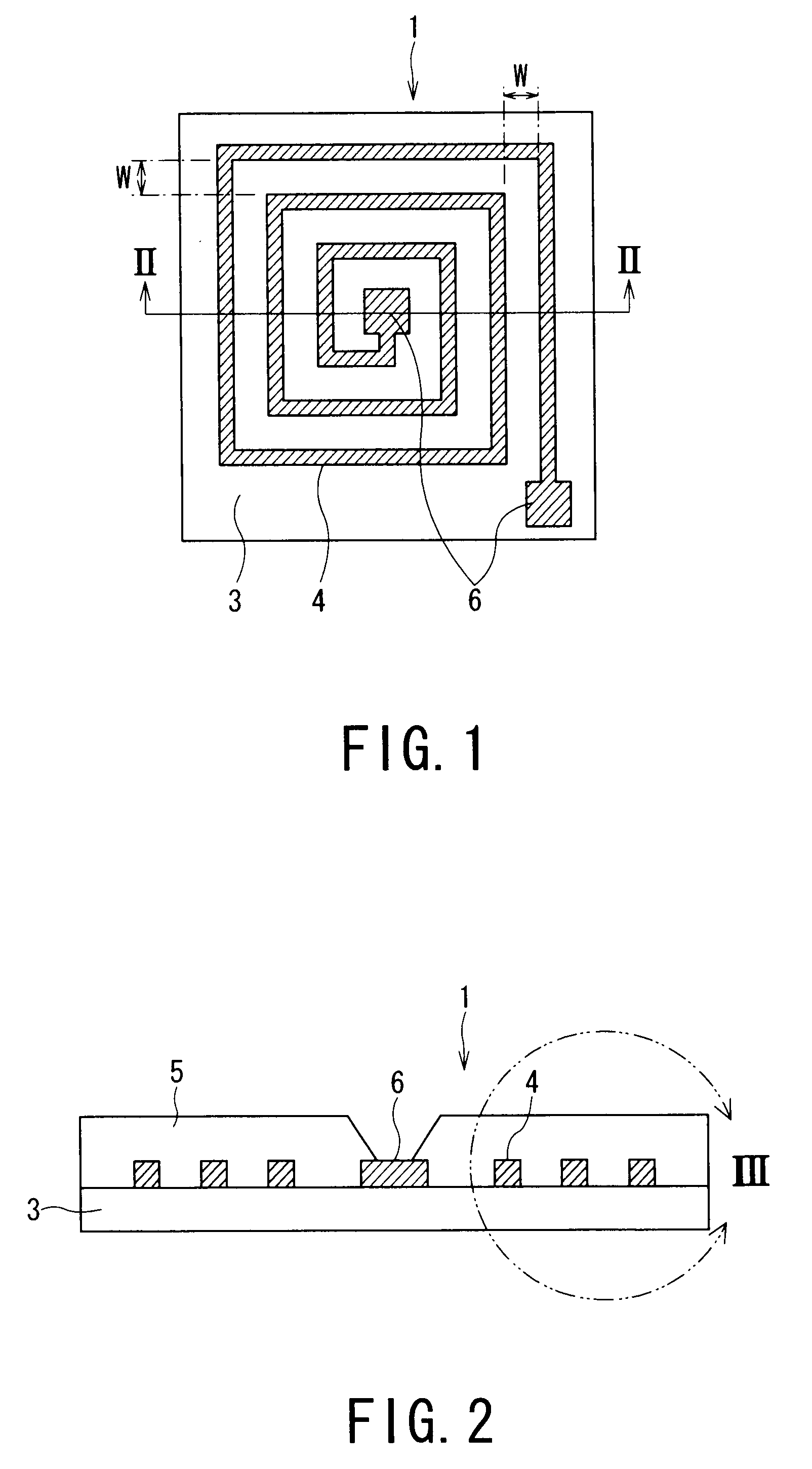
[0049]Then, the magnetic powder paste was printed at a thickness of 150 μm on a 35 μm thick polyimide sheet as a substrate 2, as shown in FIG. 3, and was then dried at 150° C. for 60 minutes to form a first magnetic layer 3.

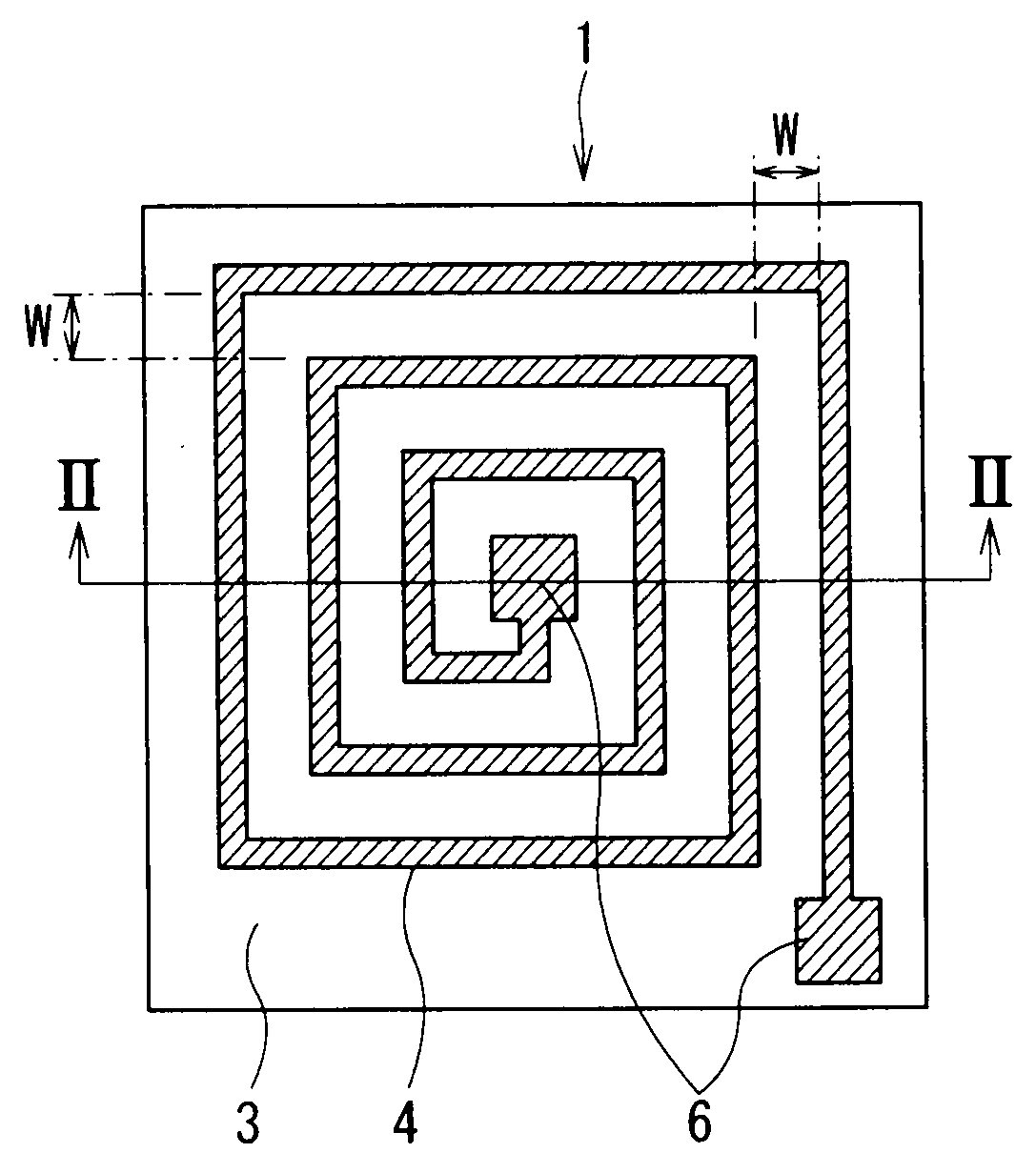
[0050]A 15-turn spiral coil as a planar coil 4 having a line width B of 150 μm and winding intervals W of 100 μm, that is, having a line / space ratio of 150 μm / 100 μm, was printed at a thickness of 20 μm on the upper surface of the first magnetic layer 3 as s...

examples 6 to 10

[0057]Magnetic material powders each having any one of the compositions shown in Table 2 were screened to prepare magnetic powders having maximum particle sizes L (maximum diameter) and average particle sizes D that are shown in Table 2. The maximum particle size shown in Table 2 is represented by the value of the opening of the screen. Each magnetic powder was mixed with an epoxy resin solution in a proportion of 11% by mass relative to the magnetic powder to prepare respective magnetic powder pastes.

[0058]Then, the magnetic powder paste was printed at a thickness of 100 μm on a 35 μm thick polyimide sheet as a substrate 2, as shown in FIG. 3, and was then dried at 150° C. for 30 minutes to form a first magnetic layer 3.

[0059]A 15-turn spiral coil as a planar coil 4 having a line width B of 100 μm and winding intervals W of 100 μm, that is, having a line / space ratio of 100 μm / 100 μm, was printed at a thickness of 25 μm on the upper surface of the first magnetic layer 3 as shown in ...

examples 11 to 15

[0063]Magnetic material powders each having any one of the compositions shown in Table 3 were screened to prepare magnetic powders having maximum particle sizes L (maximum diameter) and average particle sizes D that are shown in Table 3. The maximum particle size shown in Table 3 is represented by the value of the opening of the screen. Each magnetic powder was mixed with a polyimide resin solution in a proportion of 12% by mass relative to the magnetic powder to prepare magnetic powder pastes.

[0064]Then, the magnetic powder paste was printed at a thickness of 150 μm on a 35 μm thick polyimide sheet as a substrate 2, as shown in FIG. 3, and was then dried at 150° C. for 30 minutes to form a first magnetic layer 3.

[0065]A 15-turn spiral coil as a planar coil 4 having a line width B of 200 μm and winding intervals W of 200 μm, that is, having a line / space ratio of 200 μm / 200 μm, was printed at a thickness of 10 μm on the upper surface of the first magnetic layer 3 as shown in FIG. 1, ...


PUM

PropertyMeasurementUnit
Thicknessaaaaaaaaaa
Particle sizeaaaaaaaaaa
Distanceaaaaaaaaaa

Abstract

A planar magnetic device 1 includes a first magnetic layer 3 and a second magnetic layer 5 that are made of a mixture of a magnetic powder 7 and a resin, and a planar coil 4 disposed between the magnetic layers. When the planar coil 4 has an adjacent winding interval W between the potions 4c of the coil and the magnetic powder 7 has a maximum particle size L, planar magnetic device 1 satisfies the relationship W>L. In the planar magnetic device 1 having the above structure, fine magnetic powder that can produce a high inductance fills the spaces between the adjacent windings. Thus, the invention can achieve a high-performance planar magnetic device, such as a thin inductor.

Description

TECHNICAL FIELD[0001]The present invention relates to planar magnetic device (magnetic passive element, planar inductor) used as thin inductors, and particularly to a planar magnetic device whose magnetic permeability in the magnetic field generated in a planar coil is enhanced to increase the inductance, and to a power IC package including the same.BACKGROUND ART[0002]As electronic apparatuses have been reduced in size and weight, various devices tend to be manufactured in thin-film processes. In this trend, a planar magnetic device (planar inductor) having an external-iron structure has been proposed as magnetic devices, such as inductors (reactors), transformers, and magnetic heads, in addition to the structure in which wire is wound around a known bulk magnetic material. In the external-iron structure, a planar coil having a spiral shape or a zigzag (meander type) pattern is coated with a magnetic material. It is thus being attempted to miniaturize devices (see, for example, Non...

Claims


Application Information

Patent Timeline
IPC IPC(8): H01F27/28
CPCH01F1/26Y10T29/4902H01F17/0006H01F27/255H01F41/046H01F2017/0066H01L23/495H01L2224/16H01L2224/48091H01L2224/48247H01L2924/01025H01L2924/01078H01L2924/01079H01L2924/19041H01L2924/3011H01F1/37H01L2924/07802H01L2924/30107H01L24/48H01L2924/00014H01L2924/00H01L2924/14H01L2924/181H01F2017/0073H01L2924/00012H01L2224/45099H01L2224/45015H01L2924/207H01F17/04H01F1/20
Inventor NAKAGAWA, KATSUTOSHIINOUE, TETSUOSATO, AKIRA
Owner KK TOSHIBA
Why Eureka
Try Eureka