Light-emitting device with precisely tuned and narrowed spectral width of optical output and an optical signal source providing the same

a technology of light-emitting devices and optical outputs, which is applied in the direction of laser optical resonator construction, laser details, semiconductor lasers, etc., can solve the problem that the features of the light-emitting device are unconcerned with a type of light-generating portion, and achieve the effect of narrowing the spectral width of the light outpu

Inactive Publication Date: 2009-02-19
SUMITOMO ELECTRIC IND LTD
View PDF9 Cites 32 Cited by
  • Summary
  • Abstract
  • Description
  • Claims
  • Application Information

AI Technical Summary

Benefits of technology

[0011]When the light-generating portion provides the LED, the variable wavelength filter may provide second ring waveguide with the electrode. The vernier effect of these two ring waveguides may tune the emission wavelength and may narrow the spectral width of the light output from the device by adjusting the electrical signals applied to each ring waveguide.

Problems solved by technology

The present light-emitting device in the features thereof is unconcerned with a type of the light-generating portion.

Method used


Image

  • Light-emitting device with precisely tuned and narrowed spectral width of optical output and an optical signal source providing the same
  • Light-emitting device with precisely tuned and narrowed spectral width of optical output and an optical signal source providing the same
  • Light-emitting device with precisely tuned and narrowed spectral width of optical output and an optical signal source providing the same

Examples


first embodiment

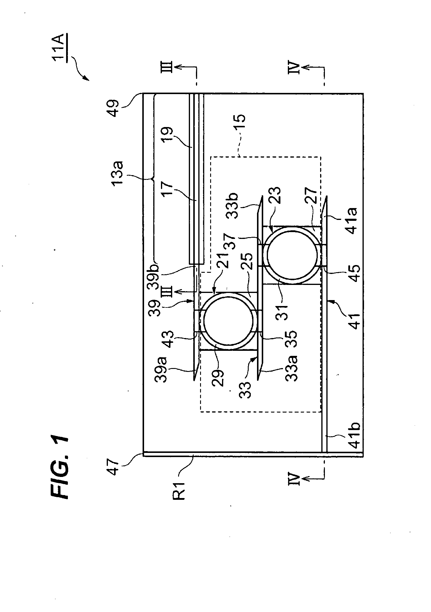
[0032]FIG. 1 schematically illustrates a semiconductor light-emitting device 11A according to the first embodiment of the invention. The device 11A is preferably applicable to the wavelength addressing system where the signal wavelengths are assigned to respective users located in short distances, typically less than a few hundred meters, or to the wavelength division multiplexing (WDM) system where the signal wavelengths are assigned to respective services. The device 11A provides a substrate, on which a light-generating portion 13a and a variable wavelength filter 15 optically coupled with the light-generating portion 13a.

[0033]In the present embodiment, the light-generating portion 13a is a type of the light emitting diode (LED) that emits super luminescent light with a wide spectrum. The light-generating portion 13a comprises a semiconductor active waveguide 17 including an active layer that generates light by injecting carriers therein and an electrode 19 to inject carriers in...

second embodiment

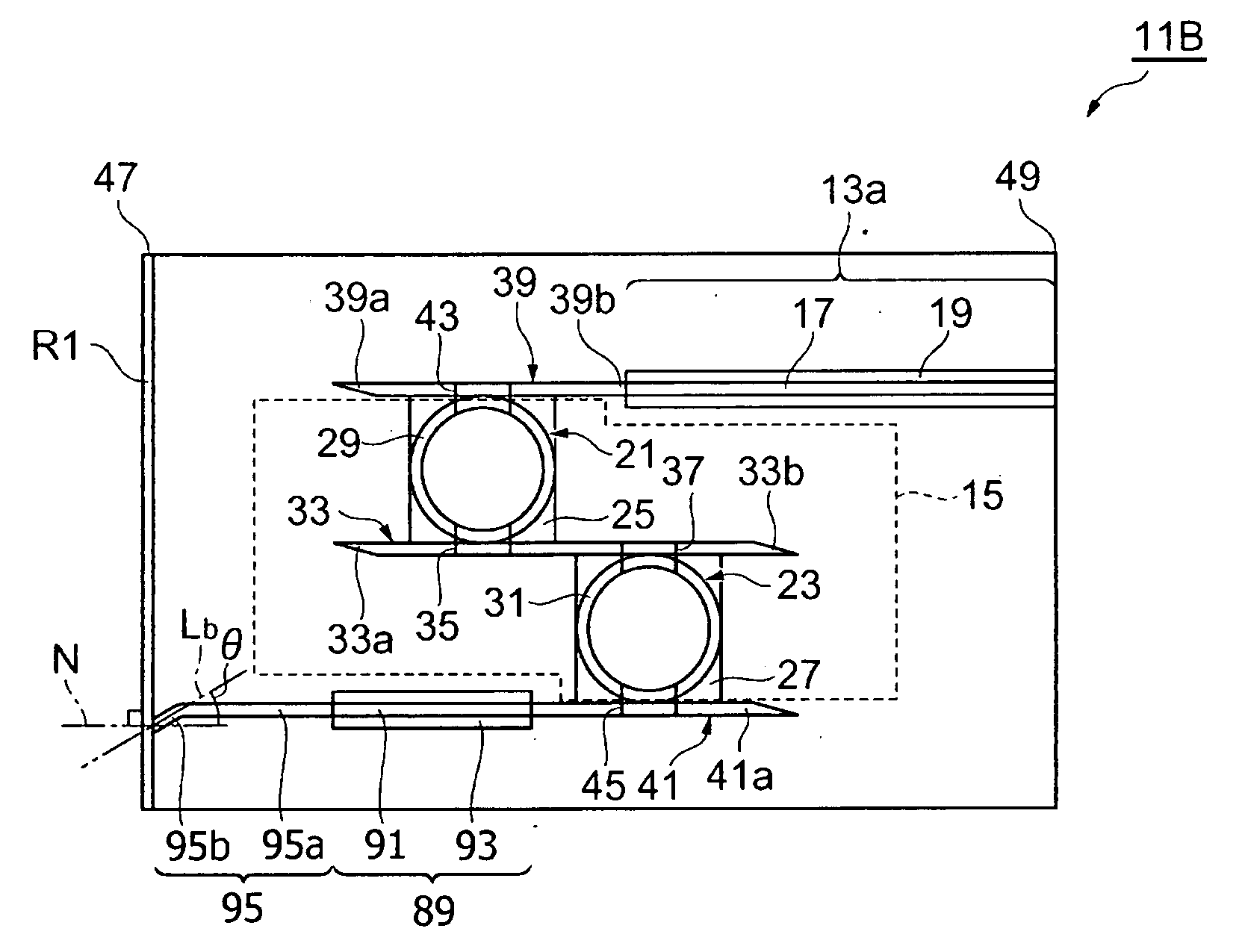
[0054]FIG. 6 is a plane view schematically showing a light-emitting device 11B according to the second embodiment of the present invention. The device 11B shown in FIG. 6 has the same configuration with those of the first embodiment except that the present device 11B provides a semiconductor optical amplifier (hereafter denoted as SOA) 89 built on the substrate S and provides a the third semiconductor waveguide 95 between the SOA 89 and the facet 47.

[0055]The SOA 89 is arranged between the variable wavelength filter 15 and the facet 47, in other word, it is formed in an extended portion of the semiconductor waveguide 41. The SOA 89, optically coupled with the variable wavelength filter 15 through the waveguide 41, amplifies the light output from the filter 15. The arrangement of the SOA 89 may be similar to those known in the fields, for instance, the SOA 89 may provide an active waveguide 91 including an active layer and an electrode 93 on the active waveguide 91 to inject carriers...

third embodiment

[0059]FIG. 7 is a plane view schematically showing a light-emitting device 11C according to the third embodiment of the invention. The device 11C has the same arrangement with the device 11A already described except that, in the present device 11C, the waveguide 41 makes a substantial angle e with respect to the normal N of the facet 47. The angle E between the axis L of the waveguide 41 and the facet 47 may be 3 to 12°, which is comparable to the bent angle of the waveguide 85 of the previous device 11B. The device 11C may be obtained such that the light-generating portion 13a and the variable wavelength filter 15 are firstly formed on the substrate S as already explained in the first embodiment and the substrate S is cut or cleaved such that the axis L of the waveguide 41 makes the angle θ with respect to the facet 47.

[0060]In the device 11C, the light propagating in the waveguide 41 enters the facet 47 with the substantial angle as already explained, which effectively controls so...


PUM


Abstract

A light-emitting device whose output wavelength is easily variable is disclosed. The device provides a light-generating portion that emits light by the carrier injection and a variable wavelength filter that sets a specific wavelength λr. The variable wavelength filter includes two ring waveguide optical coupled with each other and having optical paths different from each other and at least an electrode to apply an electrical signal to the corresponding ring waveguide. By tuning the specific wavelength λr to the wavelength emitted from the light-generating portion, the output wavelength from the light-emitting device may be narrowed.

Description

BACKGROUND OF THE INVENTION[0001]1. Field of the Invention[0002]The present invention relates to a light-emitting device with a precisely tuned output wavelength and extremely narrowed spectral width of the optical output, and an optical signal source providing such a light-emitting device.[0003]2. Related Prior Art[0004]Conventionally, a light source in which a light emitting diode (LED) is a primary light-emitting device shows an output wavelength distributing in a wide range. Such a light source may be applicable only to a system with a slow transmission speed and a short distance because the wide range of the spectrum of the optical source inevitably accompanies with the large dispersion of the optical fiber.[0005]While, another light source providing a laser diode as a primary light-emitting device also accompanies with a spread spectrum when the laser diode is directly modulated at a high speed, which is called as the chirp phenomenon, even when the laser diode is a type of th...

Claims


Application Information

Patent Timeline
Patent Type & Authority Applications(United States)
IPC IPC(8): H01S3/10H01S5/12
CPCH01S5/0078H01S5/0085H01S5/026H01S5/50H01S5/12H01S5/141H01S5/1032
Inventor KATO, TAKASHI
Owner SUMITOMO ELECTRIC IND LTD
Why Eureka
Try Eureka