Optical coupler for a light emitting device with enhanced output brightness

a light emitting device and optical coupler technology, applied in the field of optical couplers, can solve the problems of limited brightness and power output of light sources, and achieve the effect of increasing light coupling efficiency and increasing output brightness

Active Publication Date: 2009-02-26
YLX INC
View PDF10 Cites 19 Cited by
  • Summary
  • Abstract
  • Description
  • Claims
  • Application Information

AI Technical Summary

Benefits of technology

[0007]An object of the present invention is to provide a light source with enhanced output brightness.
[0008]Another object of the present invention is to provide a coupling apparatus and method for collecting light from a light emitting device with increased light coupling efficiency.

Problems solved by technology

The brightness and power output of a light source are often limited by the light coupling efficiency in which light from the light emitting devices such as LEDs into the waveguide or optical fiber.

Method used


Image

  • Optical coupler for a light emitting device with enhanced output brightness
  • Optical coupler for a light emitting device with enhanced output brightness
  • Optical coupler for a light emitting device with enhanced output brightness

Examples


Embodiment Construction

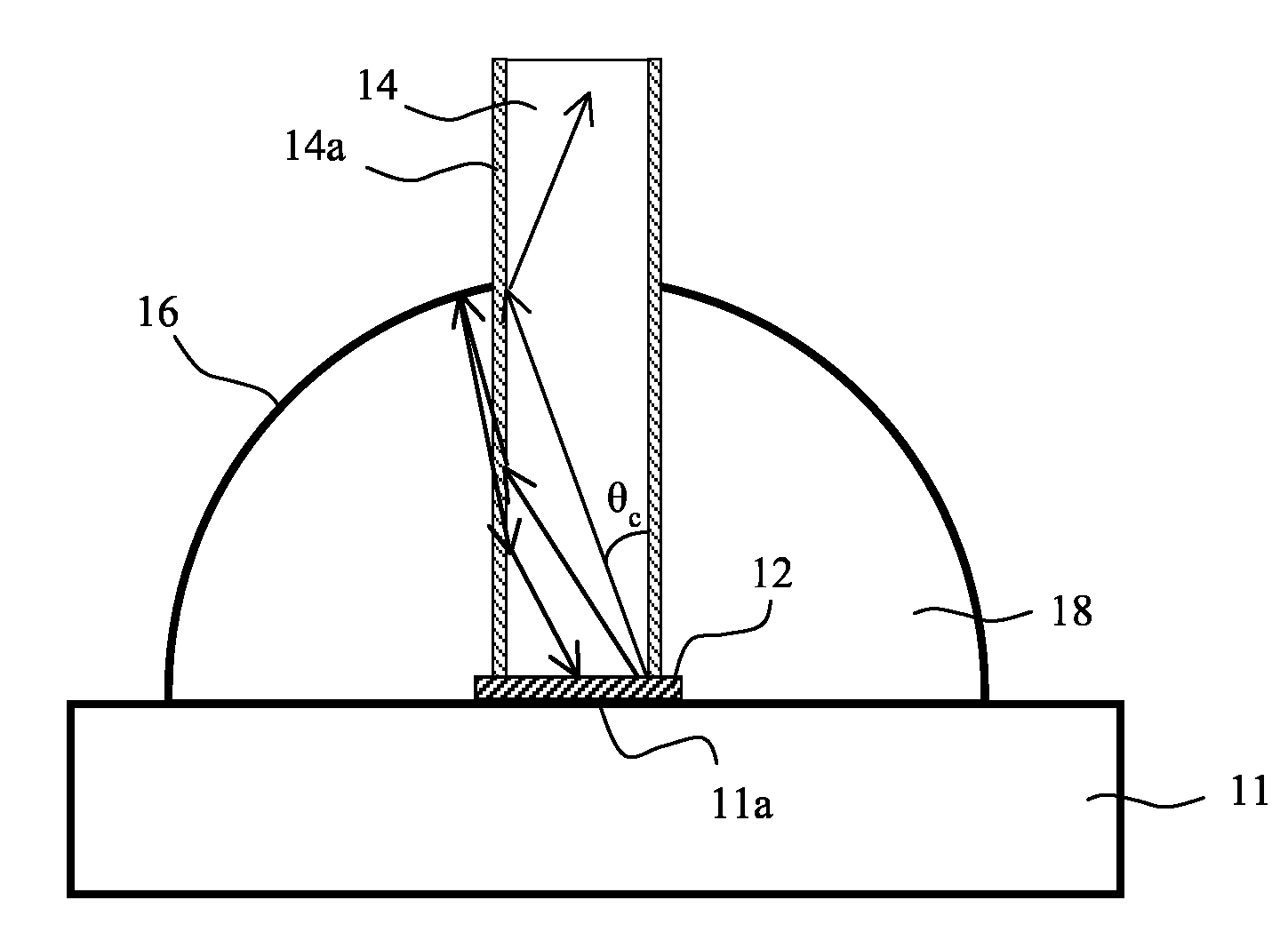
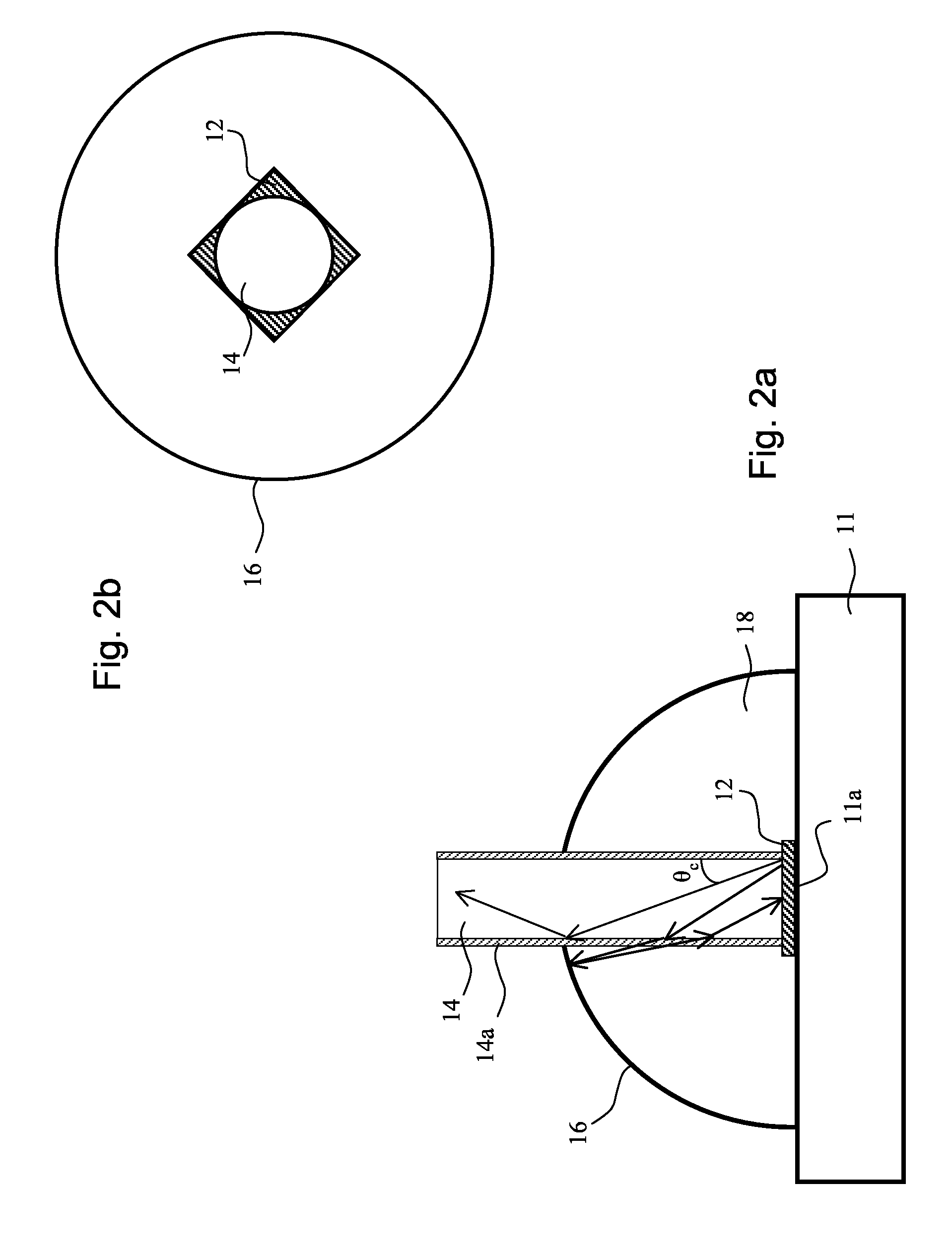
[0020]Embodiments of the present invention provide a light source where the light emitted by a light emitting device is coupled into an optical waveguide. It employs a highly reflective coupler (reflector) which helps to recycle the light from the light emitting device that falls outside of the numerical aperture of the waveguide back to the light emitting device, thereby increasing the coupling efficiency and enhancing the output brightness of the light source. The light emitting device may be a light emitting diode (LED), a laser diode, or other solid-state light emitting devices. The light emitting device may also be a wavelength conversion material such as a phosphor that converts a shorter wavelength light to a longer wavelength light, or any other suitable device that emits light. An LED is used as an example in the embodiments shown in FIGS. 2a-5.

[0021]In a first embodiment of the present invention illustrated in FIGS. 2a and 2b, an LED chip 12 is mounted on a substrate 11. A...


PUM


Abstract

A light source is described where the light emitted by a solid-state light emitting device such as an LED is coupled into an optical waveguide such as an optical fiber. A highly reflective coupler (reflector) is disposed around the LED and a segment of the waveguide adjacent the LED. Light emitted from the LED that falls outside of the numerical aperture of the waveguide leaks out of the waveguide, but is reflected back to the waveguide by the reflector. The reflected light is re-reflected or scattered by the LED or the substrate the LED is mounted on, and the re-reflected or scattered light that falls within the numerical aperture of the waveguide is coupled into the waveguide. As a result, light coupling efficiency is increased and the output brightness of the light at the other end of the fiber is enhanced.

Description

BACKGROUND OF THE INVENTION[0001]1. Field of the Invention[0002]This invention relates to light sources, and in particular, it relates to light sources using solid state light emitting devices.[0003]2. Description of the Related Art[0004]Solid state light sources, such as light emitting diodes (LEDs), exhibit longer lifetimes, lower power consumption, manageable wavelengths and other benefits in comparison with traditional light sources such as high-pressure mercury lamps, Xenon lamps or metal halide lamps. These solid-state light sources increasingly become the alternative or even preferred choice of light sources for a variety of applications, including image projection such as rear projection TV (RPTV) or front projector, headlights or illumination lights for transportation vehicles such as automobiles, motorcycles, boats and airplanes, etc. One import requirement for a light source is to provide high brightness and high power output at the same time.[0005]In many applications, t...

Claims


Application Information

Patent Timeline
Patent Type & Authority Applications(United States)
IPC IPC(8): G02B6/42G02B6/12
CPCG02B6/4298G02B6/4214
Inventor YANG, YIXU, LILI, YI
Owner YLX INC
Why Eureka
Try Eureka