Fuel cell, components and systems

a fuel cell and component technology, applied in the field of fuel cells, can solve the problems of embodied significant limitations, waste of roughly 83% of the mass, and much worse waste degr

Inactive Publication Date: 2009-02-26
IACOVELLI BENEDETTO ANTHONY
View PDF14 Cites 29 Cited by
  • Summary
  • Abstract
  • Description
  • Claims
  • Application Information

AI Technical Summary

Problems solved by technology

A primary byproduct is water, but conventional fuel cell designs inevitably yield several more undesired byproducts such as carbon monoxide, sulfur, and the like, particularly when employing a carbon-based fuel.
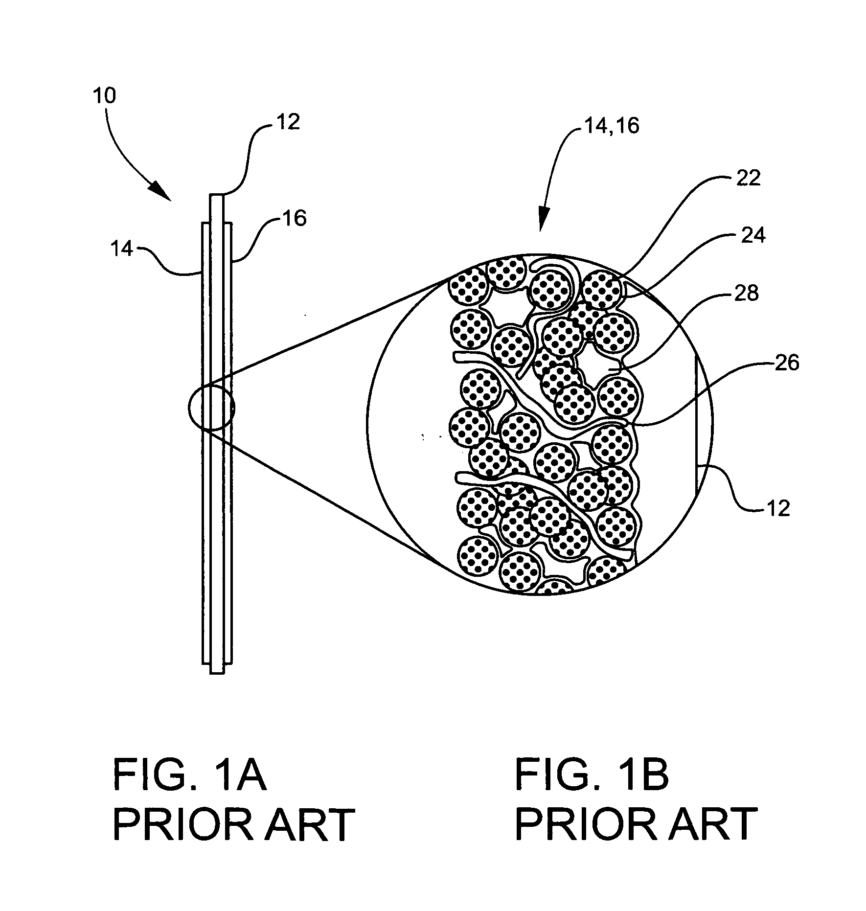
The current design as exemplified by membrane electrode assembly 10 illustrated in FIGS. 1A and 1B is functional and an improvement over earlier designs, but it is still embodies significant limitations.
It follows that only about ⅙th or 17% of the platinum is potentially available as a catalyst, such that roughly 83% of the mass is wasted.
The degree of waste is much worse in direct methanol fuel cells, which require larger particles and heavier catalyst loadings.
The remaining portion of the catalyst is potentially wasted, for instance, by being locked inside the particle.
This contact area excludes contact with the reactants and thus further limits the usable, catalytic surface area.
Additionally, a yet additional loss of catalytic utilization occurs because the reaction can only take place at the triple-interface of the fuel, electrolyte, and catalyst.
Furthermore, those particles that do experience a favorable interface produce or use water, thereby changing the fuel / water ratio in their immediate microenvironment, often decreasing catalytic efficiency.
Another problem is that the materials and mixtures utilized in the prior art are fairly electrically resistant.
This internal resistance substantially decreases electrical production efficiency and necessitates the use of conductive current-collecting “field flow” plates that add sizeable cost and volume to the fuel cell or fuel cell stack.
In addition, the carbon-platinum mixture utilized in prior art approaches is essentially a brittle composition of dust or a composite of powders.
Over time the mixture tends to disintegrate and thereby limit lifespan and efficiency.
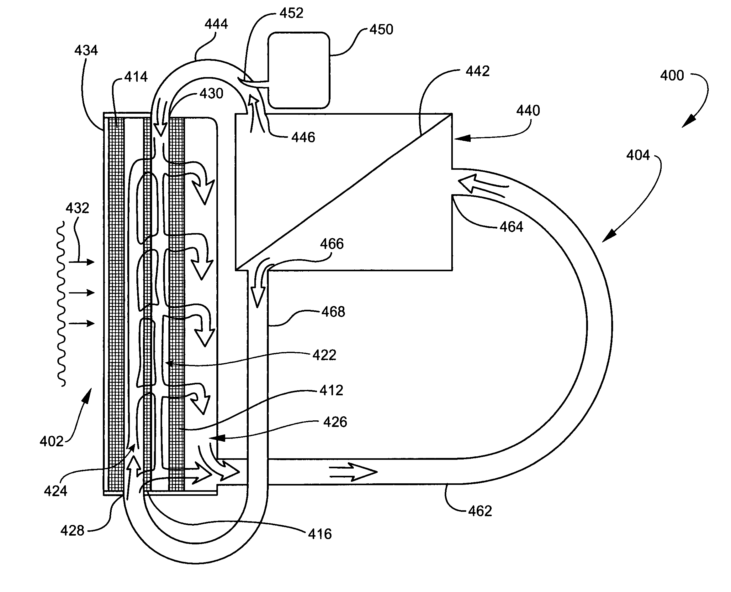
Moreover, in current fuel cell designs, the fuel flows by and diffuses into the anode but not though it.
Consequently, inert compounds can build up in the pores and physically block the fuel from reaching the catalyst, hence further limiting efficiency.
Water is produced at one electrode and thus can potentially flood the electrode.
To ameliorate or compensate for these flooding and drying events, current fuel cell designs must resort to the addition of extensive, costly and power-robbing balance-of-plant apparatus.
Much of the prohibitive cost of fuel cell production can be attributed to the balance-of-plant and not the fuel cell stack itself.
Unfortunately, even with the use of balance-of-plant apparatus, the simultaneous ideal humidification for each electrode (anode and cathode, as well as the electrolyte) is never quite uniformly achieved.
Poisoning and contamination remain a pervasive problem in many fuel cell designs.
Catalysts suffer from poisoning by common contaminants found in many fuel stocks.
Over time, these substances adhere to the catalytic particles of conventional electrodes, degrading their performance and limiting their lifespan.
Sensitivity to poisoning seriously limits the feasibility and commercial viability of the currently existing technologies.
It is especially a problem in fuel cells that use currently available fossil fuels and natural gas derivatives.
These fuels have relatively high amounts of sulfur compounds and complex hydrocarbons that form a variety of toxic intermediary compounds.
To partially atone for this problem, manufacturers are forced to incorporate expensive, additional balance-of-plant apparatus such as those noted above, particularly fuel stock scrubbers, reformers, shift reactors, and advanced filters, all of which can be bulky and / or expensive and escalate inefficiency, maintenance requirements, and pollution.
The extra equipment also requires energy to run that is parasitically drawn from the output of fuel cell.

Method used


Image

  • Fuel cell, components and systems
  • Fuel cell, components and systems
  • Fuel cell, components and systems

Examples


Embodiment Construction

[0058]In general, the term “communicate” (e.g., a first component “communicates with” or “is in communication with” a second component) is used herein to indicate a structural, functional, mechanical, electrical, magnetic optical, fluidic, or ionic transporting, relationship between two or more components or elements. As such, the fact that one component, element, or feature is said to communicate with a second component, element, or feature is not intended to exclude the possibility that additional components may be present between, and / or operatively associated or engaged with, or otherwise interacting with, the first and second components.

[0059]As used herein, the term “fluid” generally means any flowable medium such as a liquid, gas, vapor, supercritical fluid, or combinations thereof. Moreover, the term “fluid” encompasses mixtures or combinations of liquids, vapors, gases and supercritical fluids with solid particulate matter, as in the case of particles carried in a fluid flo...


PUM

PropertyMeasurementUnit
thicknessaaaaaaaaaa
pore sizeaaaaaaaaaa
pore sizeaaaaaaaaaa

Abstract

Alkali fuel cells, systems, and related methods, and flow-through, high-surface area electrodes, are employed to generate electricity. The electrode can include a porous substrate comprising a first side for fluid ingress, a second side for fluid egress, and a plurality of walls oriented in different directions between the first and second sides. Voids can be defined between the walls. The walls can include surfaces and micro-scale pores. A multi-directional fluid flow path can be defined between the first and second sides. A thin film comprising a catalytic material can be disposed on the surfaces. A fuel / electrolyte mixture can be flowable generally from the first side, through the voids and the pores of the substrate and in contact with the thin film, and to the second side. Additives can be included for refreshing the electrolyte and / or the electrode. A water / thermal / pressure management system includes a permeable membrane from which water can be removed from a fluid while retaining fuel and / or electrolyte in the fluid. The electrolyte can include an additive that cleans the electrodes. A refresh cycle can be implemented in which one or more electrodes are operated in a mode that refreshes catalytic material of the electrode.

Description

CROSS-REFERENCE TO RELATED APPLICATIONS[0001]This application claims priority to U.S. Provisional Patent Application Ser. No. 60 / 464,874 filed Apr. 22, 2003, entitled “Improved Designs for a Reduced Cost Flexible Fuel Methanol Capable Fuel Cell and Components”; and U.S. Provisional Patent Application Ser. No. 60 / 500,123 filed Sep. 3, 2003, entitled “Reduced Cost Flexible Fuel Methanol Capable Fuel Cell and Components”; the contents of each of which are incorporated herein by reference in their entireties.BACKGROUND OF THE INVENTION[0002]1. Field of the Disclosure[0003]The present invention relates generally to fuel cells. More particularly, the present invention relates to fuel cells utilizing flow-through electrodes and alkali electrolytes.[0004]2. Background of the Disclosure[0005]In general terms, a fuel cell generates DC electricity by a chemical reaction or reactions occurring at an anode and a cathode. The electricity is utilized by an electrical circuit communicating with the...

Claims


Application Information

Patent Timeline
Patent Type & Authority Applications(United States)
IPC IPC(8): H01M8/04H01M4/86H01M2/14H01MH01M4/88H01M4/92H01M8/02H01M8/08
CPCH01M4/8626H01M4/921H01M4/923Y02E60/50H01M8/0232H01M8/083H01M8/086H01M4/926
Inventor IACOVELLI, BENEDETTO ANTHONY
Owner IACOVELLI BENEDETTO ANTHONY
Why Eureka
Try Eureka