Solar cell and fabricating process thereof

a solar cell and fabricating technology, applied in the field of photoelectric components and fabricating processes thereof, can solve the problems of insufficient energy conversion efficiency of the overall solar cell, insufficient blue light absorption of the solar cell, and undesirable electric conductivity of the emitter layer b>12/b>, so as to reduce the recombination rate of electron-hole pairs, reduce contact resistance, and increase the effect of blue light absorption

Inactive Publication Date: 2009-03-05
MOSEL VITELIC INC
View PDF7 Cites 33 Cited by
  • Summary
  • Abstract
  • Description
  • Claims
  • Application Information

AI Technical Summary

Benefits of technology

[0010]It is an object of the present invention to provide a solar cell and a fabricating procedure thereof in order to reduce the contact resistance between the first electrode and the emitter layer, reduce the recombination rate of the electron-hole pairs at the surface of the solar cell, increase the blue light absorption and enhance the energy conversion efficiency of the overall solar cell.

Problems solved by technology

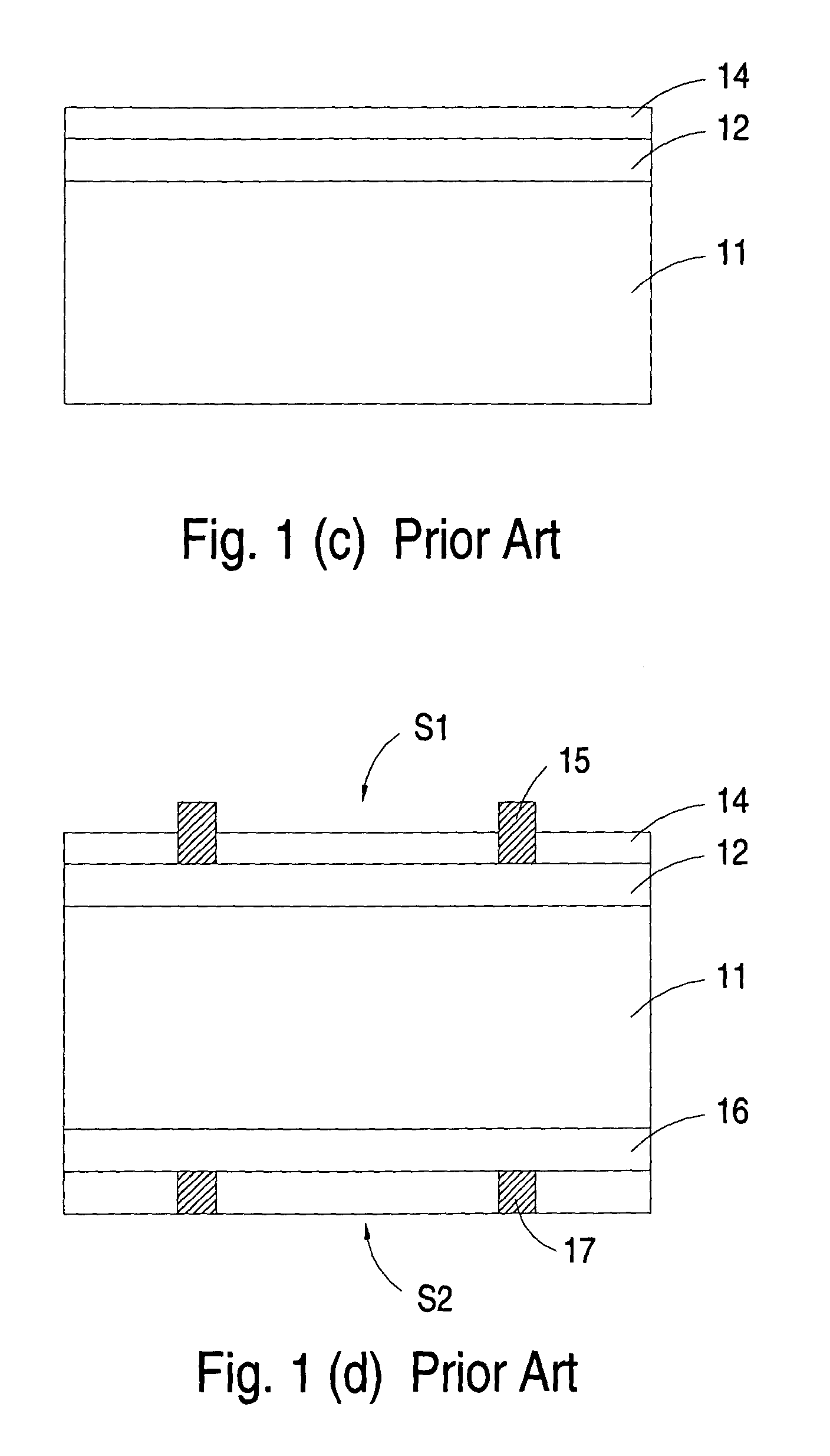
Although the solar cell produced by the above procedure has good PV effect, there are still some drawbacks.
For example, since the emitter layer 12 is implanted with low n-type dopant concentration, the electric conductivity of the emitter layer 12 is usually undesirable.
Under this circumstance, however, the recombination rate of the electron-hole pairs at the surface of the solar cell is increased, and thus the blue light absorption of the solar cell and the energy conversion efficiency of the overall solar cell are insufficient.

Method used


Image

  • Solar cell and fabricating process thereof
  • Solar cell and fabricating process thereof
  • Solar cell and fabricating process thereof

Examples


Embodiment Construction

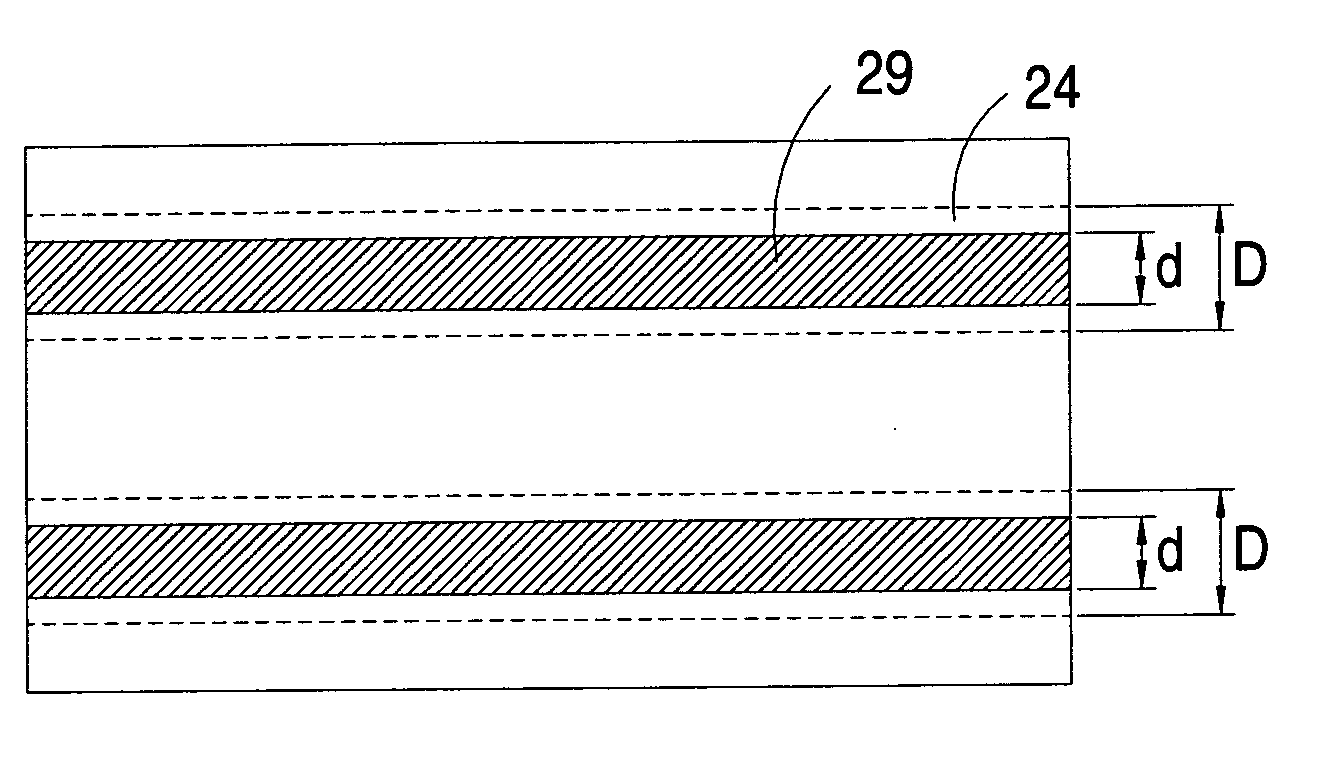
[0017]The present invention will now be described more specifically with reference to the following embodiments. It is to be noted that the following descriptions of preferred embodiments of this invention are presented herein for purpose of illustration and description only. It is not intended to be exhaustive or to be limited to the precise form disclosed.

[0018]Hereinafter, a process of fabricating a solar cell according to a preferred embodiment of the present invention will be illustrated as follows with reference to FIGS. 2(a)˜2(f).

[0019]First of all, as shown in FIG. 2(a), a first semiconductor substrate 21 is provided. An example of the first semiconductor substrate 21 includes but is not limited to a p-type semiconductor substrate. Next, concave and convex patterns with a minute pyramidal shape called as a texture are formed on the surface of the first semiconductor substrate 21 in order to improve light absorption and reduce light reflectivity. The texture structure is very...


PUM


Abstract

A solar cell includes a semiconductor substrate, an emitter layer, at least one emitter contact region and at least one first electrode. The emitter layer is formed on at least one surface of the semiconductor substrate. A p-n junction is formed between the emitter layer and the semiconductor substrate. The emitter contact region is formed on portions of the emitter layer and has the same type of dopant as the emitter layer. The emitter contact region has a higher dopant concentration than the emitter layer. The first electrode is coupled with the emitter contact region.

Description

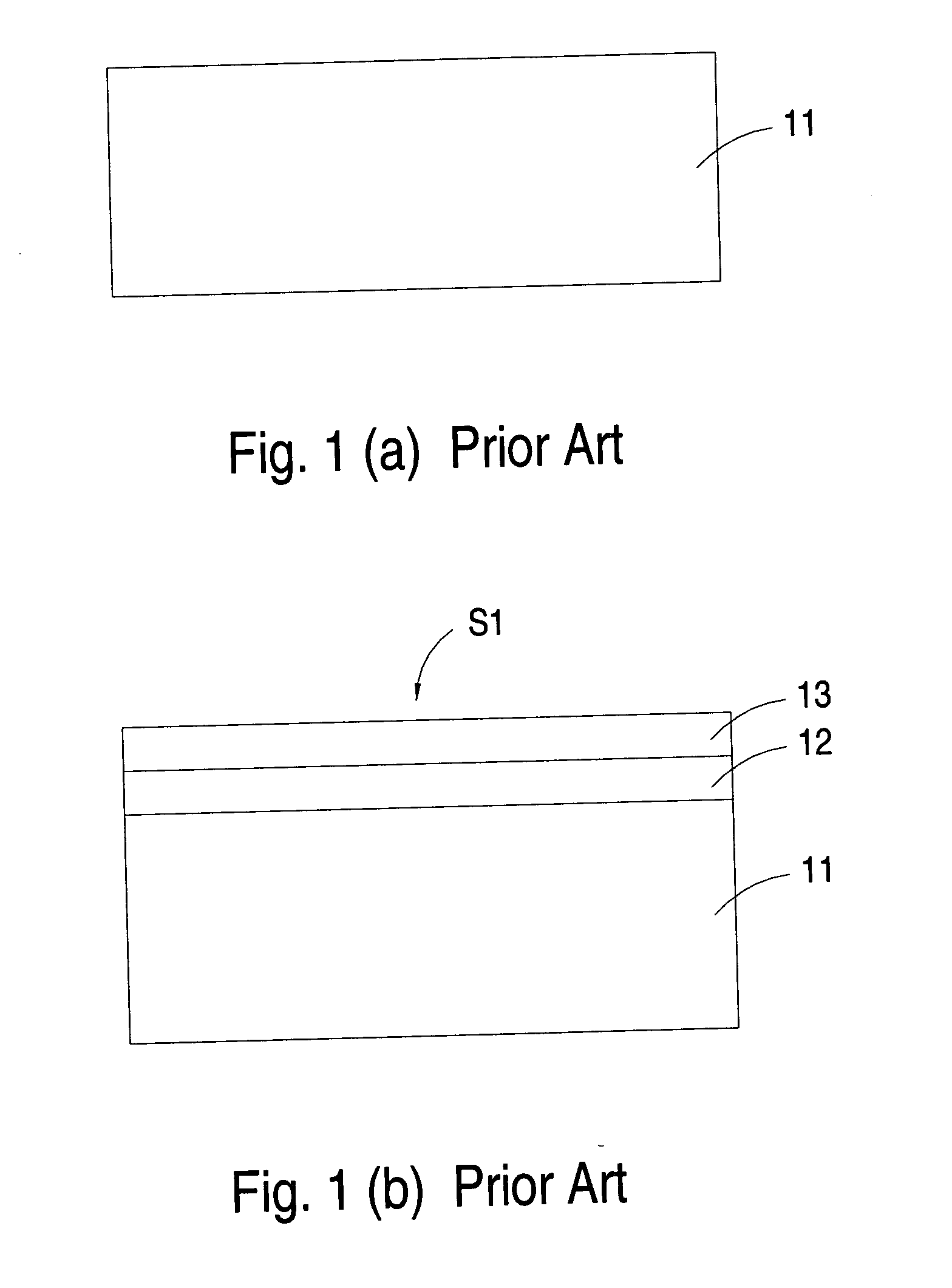
FIELD OF THE INVENTION[0001]The present invention relates to a photoelectric component and a fabricating process thereof, and more particularly to a solar cell and a fabricating process thereof.BACKGROUND OF THE INVENTION[0002]Recently, the ecological problems resulted from fossil fuels such as petroleum and coal have been greatly aware all over the world. Consequently, there are growing demands on clean energy. Among various alternative energy sources, a solar cell is expected to replace fossil fuel as a new energy source because it provides clean energy without depletion and is easily handled. A solar cell is a device that converts light energy into electrical energy. The procedure of turning solar energy into electric energy is called the photovoltaic (PV) effect.[0003]Hereinafter, a conventional process of fabricating a solar cell is illustrated as follows with reference to FIGS. 1(a)˜1(d).[0004]First of all, as shown in FIG. 1(a), a p-type semiconductor substrate 11 is provided...

Claims


Application Information

Patent Timeline
Patent Type & Authority Applications(United States)
IPC IPC(8): H01L31/028H01L31/04H01L21/00
CPCH01L31/022425H01L31/02363Y02E10/547H01L31/1804H01L31/1864H01L31/068Y02P70/50
Inventor CHEN, HSI-CHIEHCHU, CHIH-HSUN
Owner MOSEL VITELIC INC
Why Eureka
Try Eureka