Coating on a fiber substrate and a coated fiber product

a technology of coating and fiber substrate, which is applied in the direction of film/foil adhesives, instruments, manufacturing tools, etc., can solve the problems of large vacuum pumping period time- and energy-consuming, inability to achieve industrial scale coating of most of the present fiber products, and inability to clean up after vacuuming

Inactive Publication Date: 2009-03-05
PICODEON OY
View PDF30 Cites 15 Cited by
  • Summary
  • Abstract
  • Description
  • Claims
  • Application Information

AI Technical Summary

Benefits of technology

[0001]The invention relates generally to a method for coating fiber products comprising large surface areas by ultra short pulsed laser ablation. The invention also relates to products manufactured by the method. The invention has many advantageous effects such as high coating production rate, low-temperature coating conditions accomplishing coating of fiber-products, excellent coating properties and low manufacturing costs.
[0002]The fibers can be divided to natural fibers such as various cellulosic fibers from lignocelluloses, and to man-made fibers. Artificial fibers are commonly divided to main groups, namely mineral fibers and polymer fibers.
[0003]The most well-known mineral fibers are glass and metal fibers, such as fiberglass, optical fibers, metallurgic fibers and carbon fibers.
[0004]The polymer fibers are a subset of man-made fibers, which are based on synthetic chemicals (often from petrochemical sources) rather than arising from natural materials by a purely chemical process. Such fibers are typically made from polyamide (nylon), PET or PBT polyester, phenol-formaldehyde (PF), polyvinyl alcohol fiber (PVOH), polyvinyl chloride fiber (PVC), polyolefins (PP and PE), acrylic polymers such as pure polyacrylonitrile PAN and various aromatic polyamids such as Twaron, Kevlar and Nomex. Additionally, one can mention polyethylene (PE), HMPE; elastomers and polyurethane fibers.
[0005]Fibers are employed practically everywhere as in paper&board products and in various textiles for human, technical, exterior and interior use.
[0006]Regardless the nature of fibers, fiber materials are bendable. They are typically heat-sensitive and are applied in forms comprising large surfaces.Laser-Ablation

Problems solved by technology

Neither recent high-technological coating methods, nor present coating techniques related to laser ablation either in nanosecond or cold ablation range (pico-, femto-second lasers) can provide any feasible method for industrial scale coating of fiber products comprising larger surfaces.
The present CVD- and PVD-coating technologies require high-vacuum conditions making the coating process batch wise, thus non-feasible for industrial scale coating of most of the present fiber products.
Moreover, the distance between the metal material to be coated and the coating material to be ablated is long, typically over 50 cm, making the coating chambers large and vacuum pumping periods time- and energy-consuming.
Such high-volume vacuumed chambers are also easily contaminated with coating materials in the coating process itself, requiring continuous and time-consuming cleaning processes.

Method used


Image

  • Coating on a fiber substrate and a coated fiber product
  • Coating on a fiber substrate and a coated fiber product
  • Coating on a fiber substrate and a coated fiber product

Examples


examples

Example to Demonstrate Known Art Problems

Laser Technology

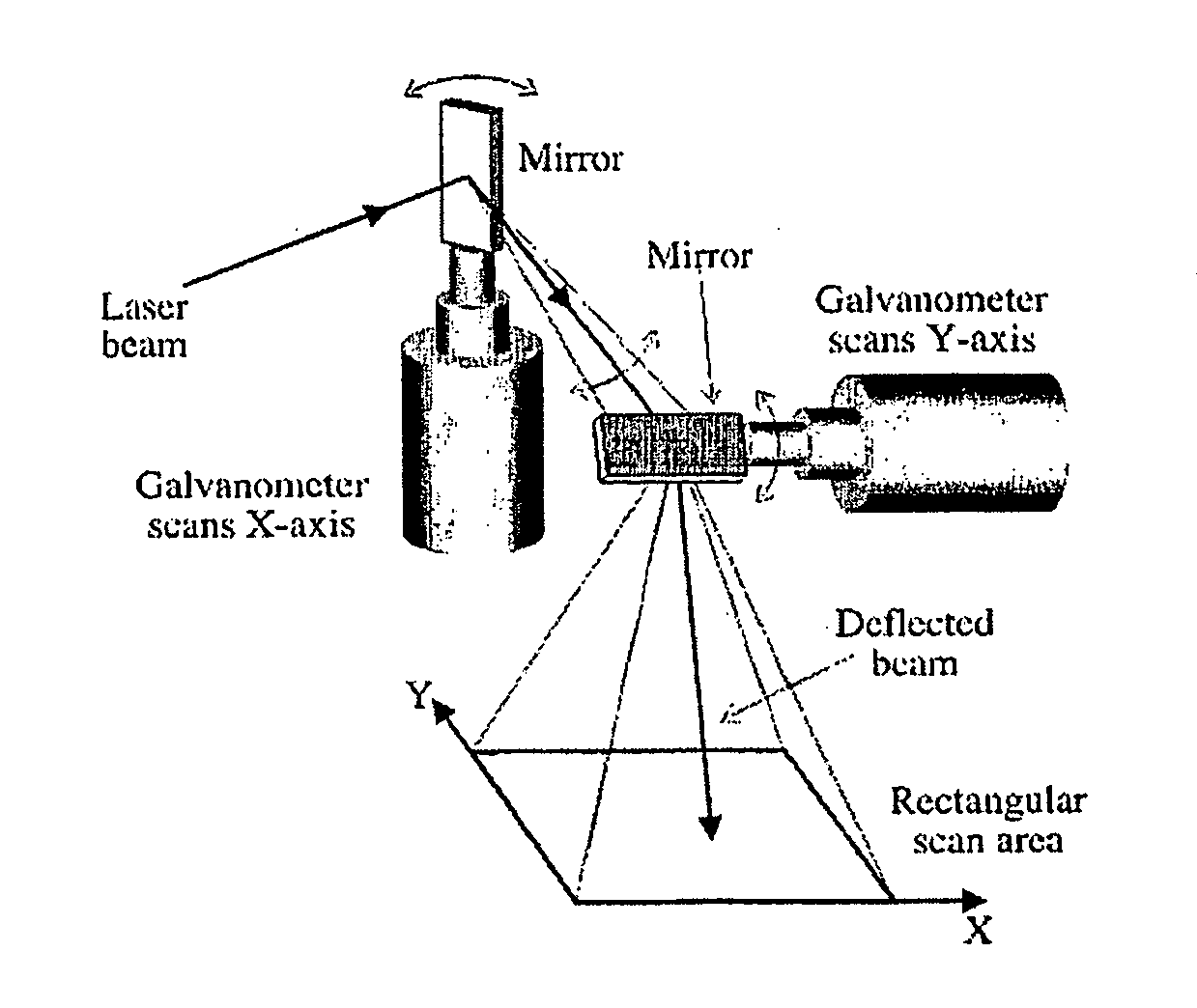
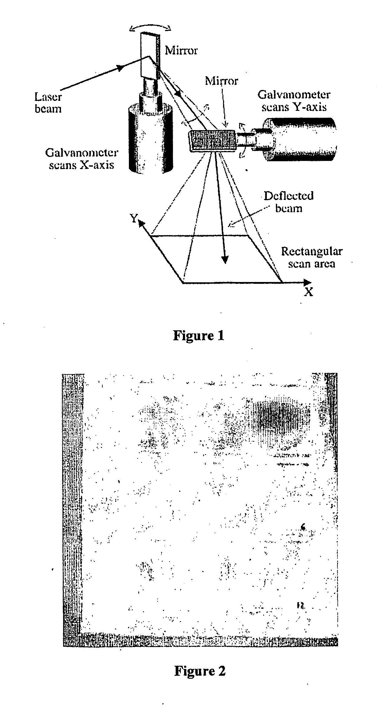
[0118]FIG. 2 represents the ITO-coating on polycarbonate sheet (˜100 mm×30 mm) produced by employing a prior art optical scanner, namely vibrating mirror (galvo-scanner), in different ITO thin-film thicknesses (30 nm, 60 nm and 90 nm). Although the ITO-coating is not deposited on metal substrate, the picture clearly demonstrates some of the problems associated with employing vibrating mirror as an optical scanner especially in ultra short pulsed laser deposition (USPLD) but also in laser assisted coatings in general. As a vibrating mirror changes its direction of angular movement at its end positions, and due to moment inertia, the angular velocity of the mirror is not constant near to its end positions. Due to vibrating movement, the mirror continuously brakes up and stops before speeding up again, causing thus irregular treatment of the target material at the edges of the scanned area. As it can be seen from FIG. 2, this in ...

example of invention

1

[0123]FIG. 9a demonstrates a target material ablated with pico-second-range pulsed laser employing rotating scanner with speed accomplishing the ablation of target material with slight overlapping of adjacent pulses, avoiding the problems associated with prior art galvano-scanners. FIG. 9b shows enlarged picture of one part of the ablated material, clearly demonstrating the smooth and controlled ablation of material on both x- and y-axis and thus, generation of high quality, particle-free plasma and further, high quality thin-films and coatings. FIG. 9c demonstrates one example of possible x- and y-dimensions of one single ablation spot achieved by one or few pulses. Here, it can be clearly seen, that the invention accomplishes the ablation of material in a manner wherein the width of the ablated spot is always much bigger than the depth of the ablated spot area. Theoretically, the possible particles (if they would be generated) could now have a maximum size of the spot depth. The ...

example 1

[0127]An ark of copy paper (80 g / m2, white, uncoated) comprising 100 mm×100 mm was coated by ablating sintered carbon with pulse repetition rate of 4 MHz, pulse energy 5 μJ, pulse length 20 ps and the distance between the target material and surface to be coated was 60 mm. The vacuum level was 10−5 atmospheres during the coating process. The process resulted in a uniform pale-brown coloured, transparent coating. The coating thickness was approximately 210 nm.


PUM

PropertyMeasurementUnit
surface areaaaaaaaaaaa

Abstract

The invention relates in general level to a method for coating fiber products including large surface areas. The invention also relates to coated fiber products manufactured by the method. The coating is carried out by employing ultra short pulsed laser deposition wherein pulsed laser beam is scanned with a rotating optical scanner including at least one mirror for reflecting the laser beam. The invention has several both industrially and qualitatively advantageous effects such as high coating production rate, low-temperature coating conditions accomplishing coating of fiber-products excellent coating properties and overall low manufacturing costs.

Description

FIELD OF INVENTION[0001]The invention relates generally to a method for coating fiber products comprising large surface areas by ultra short pulsed laser ablation. The invention also relates to products manufactured by the method. The invention has many advantageous effects such as high coating production rate, low-temperature coating conditions accomplishing coating of fiber-products, excellent coating properties and low manufacturing costs.BACKGROUNDFiber Products[0002]The fibers can be divided to natural fibers such as various cellulosic fibers from lignocelluloses, and to man-made fibers. Artificial fibers are commonly divided to main groups, namely mineral fibers and polymer fibers.[0003]The most well-known mineral fibers are glass and metal fibers, such as fiberglass, optical fibers, metallurgic fibers and carbon fibers.[0004]The polymer fibers are a subset of man-made fibers, which are based on synthetic chemicals (often from petrochemical sources) rather than arising from na...

Claims


Application Information

Patent Timeline
Patent Type & Authority Applications(United States)
IPC IPC(8): B32B5/02C23C14/30
CPCB23K26/0815C23C14/20C23C14/28Y10T428/265Y10T428/25Y10T428/273Y10T428/24355Y10T428/256Y10T428/266Y10T428/264B23K26/0821Y10T428/31678C23C14/18
Inventor RUUTTU, JARILAPPALAINEN, REIJOMYLLYMAKI, VESAPULLI, LASSEMAKITALO, JUHA
Owner PICODEON OY
Why Eureka
Try Eureka