
Method and system for monitoring and instantly identifying faults in data communication cables

a data communication cable and fault detection technology, applied in data switching networks, instruments, frequency-division multiplexes, etc., can solve the problems of data communication cables that cannot transmit data signals, data communication cables are time-consuming and labor-intensive, and may fail to transmit data signals

Active Publication Date: 2009-03-05
TWITTER INC
View PDF9 Cites 17 Cited by
  • Summary
  • Abstract
  • Description
  • Claims
  • Application Information

AI Technical Summary

Benefits of technology

[0040]The present invention provides a method and system that overcomes at least one of the current disadvantages of conventional method and system for identifying faults in data communication cables.

Problems solved by technology

Conventional data communication cables employed in a computer network environment may fail to transmit data signals.
Also, in manual testing, all computers that are linked through any suspicious data communication cable should also be removed from the network during the test, which results in a costly disruption of a normal operation.
These methods for identifying a faulty data communication cable are time consuming, labor intensive, and increase the risk of accidentally causing data communication loss between networked computers.

Method used


Image

  • Method and system for monitoring and instantly identifying faults in data communication cables
  • Method and system for monitoring and instantly identifying faults in data communication cables
  • Method and system for monitoring and instantly identifying faults in data communication cables

Examples


first embodiment

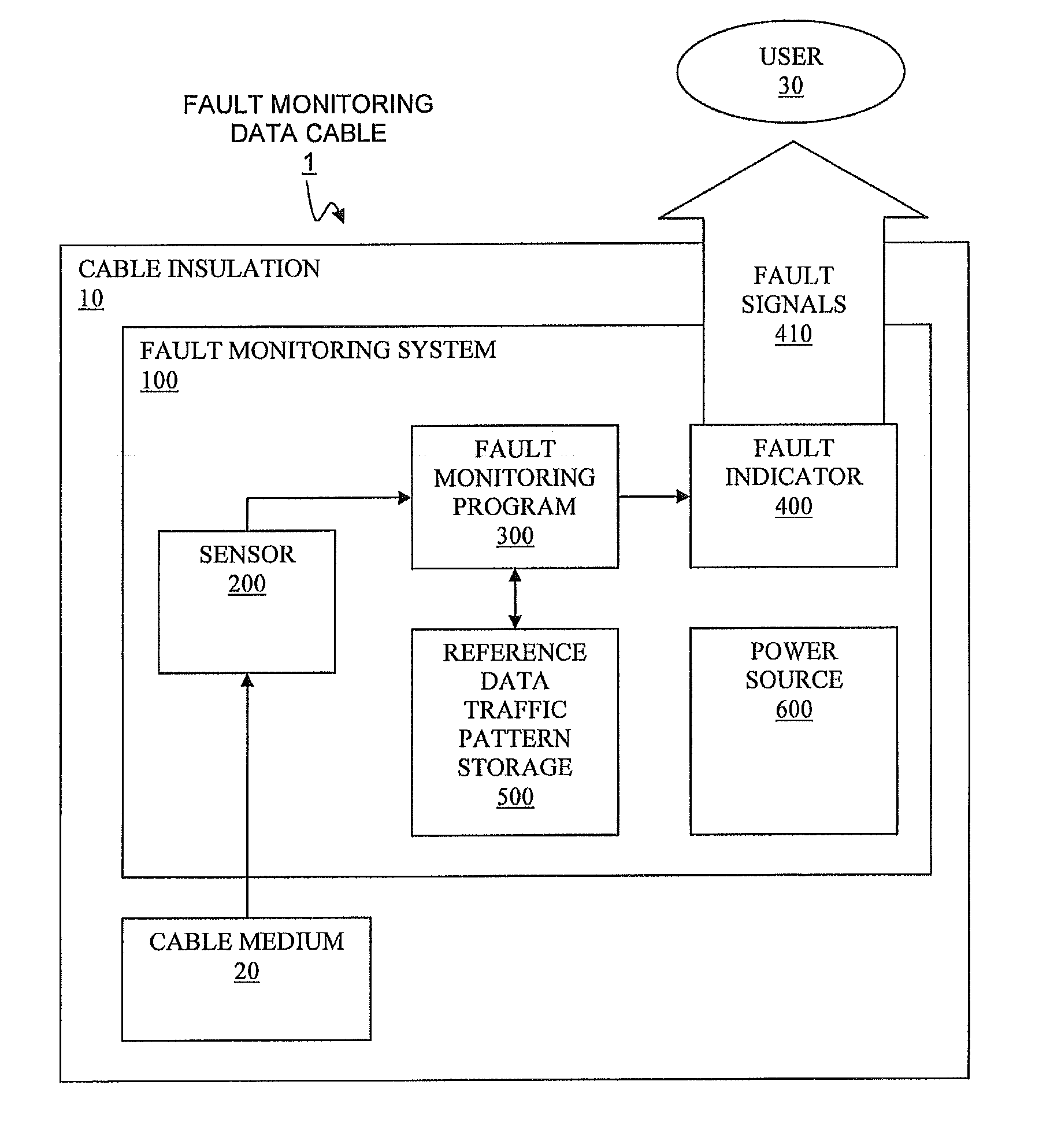
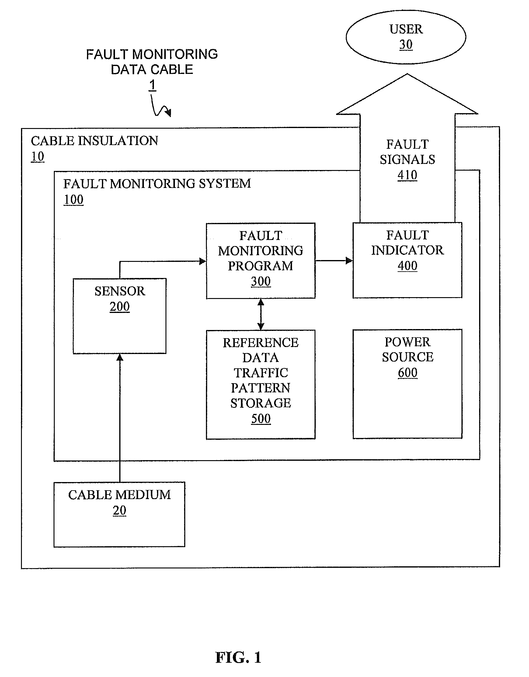
[0053]In the present invention, the sensor 200 may be, inter alia, a photon leak sensor that is implemented to detect activities within a core of optical fiber cables. In case of an optical fiber cable, the sensor must have direct line-of-sight to the glass optical core of a fiber to detect or to sample leakage photons traveling through the glass medium. A microscopic scratch or notch could be made on the surface of the glass medium to enhance the scatter of leakage photons.

second embodiment

[0054]In the present invention, the sensor may be, inter alia, an electric current sensor that is implemented to detect electric current for a metallic (e.g., copper) cable. The electric current sensor is embedded within the cable insulation 10.

third embodiment

[0055]In the present invention, the electric current sensor may be, inter alia, used with an electrical medium of a data communication cable. The electric current sensor may form a “collar” within and / or around an outer sheath covering the data communication cable, such that it works as a sensor for the fault monitoring program 300 that senses the electromagnetic field produced when even a minute electric current flows through the electrical medium of the data communication cable.

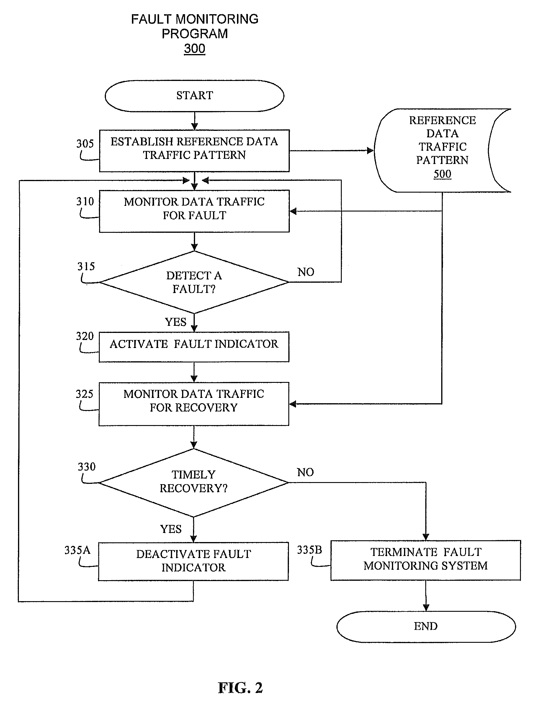
[0056]For the description on the fault monitoring program 300, see the flowchart of FIG. 2, infra.

[0057]The fault indicator 400 emits fault signals 410 to the outside of the cable insulation 10 so that the user 30 can instantly locate the fault monitoring data communication cable 1 of the present invention, in cases the fault monitoring data communication cable is faulty. The fault signals 410 that are emitted from the fault indicator 400 may be, inter alia, an audio signal, a visual signal, or a data signa...


PUM


Abstract

A method and an associated system for monitoring and instantly identifying faults in a data communication cable are disclosed. A fault monitoring program learns a reference data traffic pattern communicated through the data communication cable by reading inputs from a sensor. The reference data traffic pattern is stored and is used for determining normalcy of data traffic through the data communication cable. The fault monitoring program monitors for a fault in a data traffic, and, if a fault is detected, activates a fault indicator sending out fault signals to notify users of the fault. If the fault is not recovered within a predefined recovery period, the fault monitoring program deactivates the fault indicator and shuts down a power source for later use of the data communication cable.

Description

FIELD OF THE INVENTION[0001]The present invention discloses a method and system for monitoring and instantly identifying faults in a data communication cable.BACKGROUND OF THE INVENTION[0002]Conventional data communication cables employed in a computer network environment may fail to transmit data signals. In contemporary computer network environments, there are numerous data communication cables with identical exteriors. To locate a faulty cable, it is necessary to manually track a data communication cable from a suspected computer suffering a communication problem, or, to manually test all suspicious data communication cables if manual tracking is impossible. Also, in manual testing, all computers that are linked through any suspicious data communication cable should also be removed from the network during the test, which results in a costly disruption of a normal operation. These methods for identifying a faulty data communication cable are time consuming, labor intensive, and in...

Claims


Application Information

Patent Timeline
Patent Type & Authority Applications(United States)
IPC IPC(8): H04L12/26
CPCG01R31/021G01R31/58
Inventor BRILLHART, DAVID CLARKDAWSON, CHRISTOPHER JAMESKENDZIERSKI, MICHAEL DAVID
Owner TWITTER INC
Learn More